
Technical specifications
- Supply voltage: 5 V
- Detected colors: black, white, red, blue, and green
- Distance to the measured surface: 0–2 cm
- Detection method: reflected light
The color sensor detects the color of a surface. It combines two devices—a three-color LED and a light sensor—which can also be used separately.
How it works: The sensor combines an RGB LED, which emits red, green, and blue light, with a light-sensitive element (photoresistor) that measures the intensity of incoming light.
White light contains all the colors of the visible spectrum. A surface absorbs some colors and reflects others. By illuminating the surface with different colors and measuring the reflected light, the sensor can determine its color.
For more reliable readings:
- Keep direct and bright light off the photoresistor.
- Position the sensor so the photoresistor is shaded as much as possible.
- Leave short pauses between measurements instead of measuring continuously.
- Start a measurement only when the object is in view and stationary. Each measurement takes about 0.4 seconds; movement during that time can produce an incorrect result.
- Bring the object close to the sensor, even against the LED, to reduce interference from ambient light.
- Mount the sensor inside a housing made from the construction kit to improve accuracy.
Connection
The sensor has two standard 3-pin connectors, but they are used differently.
Connector 1 (unmarked) connects to any IN port on Trackduino. Its signal wire is connected to the photoresistor, so this connector alone lets you use the module as a light sensor.
Connector 2 (color-coded) controls the RGB LED. Its wires connect directly to the LED channels; the label shows which wire corresponds to each channel. Connect it horizontally to the signal (“S”) row, using any three OUT ports and IN ports on the controller. Connector 1 must also be connected when using only the RGB LED because its ground (GND) wire is shared by the LED and photoresistor.
Programming and calibration
The required blocks are in the “Sensors” block group. Each time a program using the color sensor starts, the “Set up color sensor” block calibrates it for the current lighting conditions:
- The RGB LED flashes white three times to indicate that calibration has started.
- Hold a reflective white surface, such as a sheet of paper, near the sensor for three seconds. The sensor then scans it in red, green, and blue.
- When the sensor turns off, hold a black surface near it within the next three seconds. It then scans the black surface in different colors.
- Calibration is complete. The program waits five seconds and resumes.
For convenience, prepare two 5 × 8 cm cards: one white and one black.
| Block and generated function | Description |
|---|---|
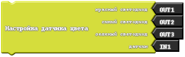 setupColorSensor(Rpin, Bpin, Gpin, Spin) | Assigns the sensor to specific ports and calibrates it.int Rpin — red LED port; int Bpin — blue LED port; int Gpin — green LED port; int Spin — port for the unmarked light-sensor wire. |
 int getColor(void) | Scans the surface and returns a color code: 0 — black; 1 — white; 2 — red; 3 — green; 4 — blue; 9 — error (the color could not be identified reliably). |
Project example
Color lock
Generated code:
void setup()
{
  setupColorSensor(OUT1, OUT2, OUT3, IN1);
  servo_port_OUT4.attach(OUT4, BIG_SERVO);
  servo_port_OUT4.write(0);
}

void loop()
{
  if (( ( getColor() ) == ( RED ) ))
  {
    servo_port_OUT4.write(100);
    delay( 15000 );
  }
  else
  {
    servo_port_OUT4.write(0);
  }
}