
Trackduino is a multifunctional controller built around the ATmega2560 processor. It has the features needed for a variety of robotics projects:
- Four motor drivers.
- A carefully designed power system.
- Power on all external ports.
- Arduino Uno interface for Arduino-compatible shields.
- Full compatibility with Arduino libraries and examples.
Specifications
- CPU: ATmega2560 (256 KB flash memory).
- Eight powered input ports (GND–Vin–S), all with ADC; ports 1–4 support interrupts; selectable 5 V/3 V supply.
- Eight powered output ports; ports 1–5 provide hardware PWM; selectable 5 V/3 V supply.
- Four DC motor ports driven by two L293 drivers with overcurrent protection.
- Standard Arduino UNO R3 interface, independent of the other I/O ports, for Arduino shields and libraries.
- Built-in Bluetooth supports sending and receiving data and flashing the microcontroller.
- microSD card slot.
- RGB LED and five programmable buttons.
- Two exposed USART ports with power (RX, TX, 5 V, GND).
- Two exposed I2C ports with power (SCL, SDA, 5 V, GND).
- Connects to a computer via USB or Bluetooth.
- Supply voltage: 7–12 V. Two power connectors: a jack for the included battery pack and a screw terminal for other power sources.
The controller board is enclosed in a case that blocks access to some ports intended for advanced users, including the external-power screw terminal, Arduino interface, IN/OUT voltage-selection jumpers (3 V or 5 V), and Bluetooth configuration jumpers. Remove the case cover to access them.
Power
The board can be powered by USB or an external source. External power can connect through the Jack connector or the screw terminal (TERM).
When multiple power sources are connected, switching works as follows:
- USB and external source: switches automatically.
- Jack and terminal: select manually with jumper XP13.
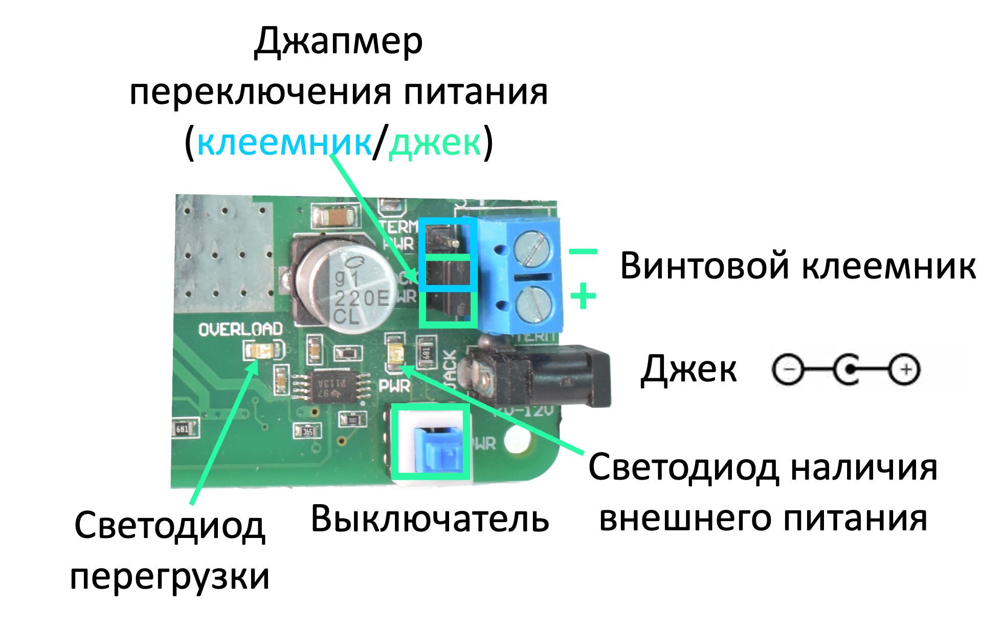
Power requirements: USB: exactly 5 V. External power: 6–17 V. External sources may include:
- 9 V battery holder (three compartments) with six AA batteries or rechargeable cells.
- Li-ion batteries with a combined voltage no higher than 17 V.
- 6–17 V DC supply rated for at least 500 mA (1–3 A when using multiple motors and servomotors).
Weak sources, such as alkaline batteries, NiMH batteries, or low-power adapters, may experience voltage drops under heavy loads, which can reset the controller. Examples of heavy loads include:
- Abruptly stopping or stalling motors.
- Reversing motors before they have stopped.
- Connecting many servomotors.
- Using servomotors to lift excessive loads.
Motor power comes directly from the external source without voltage reduction. Do not power motors above their rated voltage. Robotrack kit motors are rated for a maximum of 9 V.
USB power is recommended for projects without high-current consumers such as servomotors and motors. External power is required for projects using motors or more than two servomotors.
Motor and servomotor power: The motor-driver power stage is fed directly from the external source. Motors cannot run from USB power.
OUT ports, including those used for servomotors, are powered by USB or the external source (automatic switching) through a regulator rated for up to 500 mA. This is enough for external devices and one or two servomotors. If more than two servomotors draw more than 500 mA, the OUT overload LED turns on. Use an external source and set jumper XP9 to HIGH; the 5 V OUT ports can then supply up to 3 A.
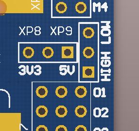
Important: With the jumper at HIGH, OUT ports are powered only by the external source and have no power when using USB. To power OUT ports from USB, set the jumper to LOW.
Power button behavior:
- External power only: turns the whole device on or off.
- USB only: has no effect (the motor drivers are unpowered).
- USB and external power together: switches power to the motor drivers only. This lets you program over USB without motors unexpectedly starting when programming finishes.
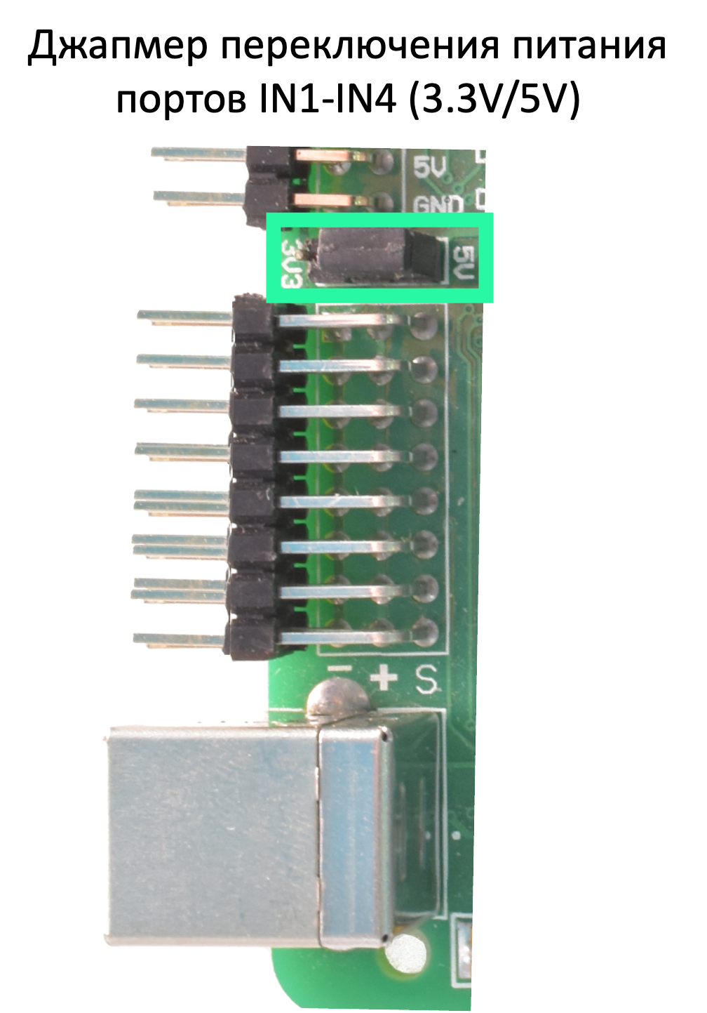
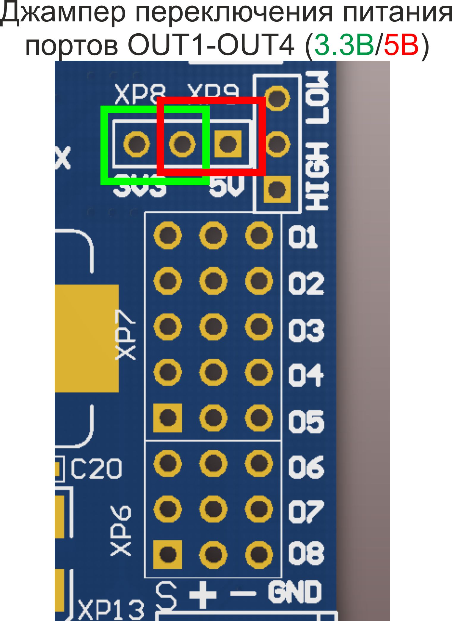
Switching between 3 V and 5 V: The voltage on input ports IN1–IN4 and output ports OUT1–OUT4 can be switched between 5 V and 3 V with the jumpers above IN1 and OUT1. This is useful for third-party 3 V sensors. The default is 5 V. Remove the case cover to access the jumpers. Robotrack kit electronics operate at 5 V.
Ports
Trackduino has multiple ports for external devices. The IN and OUT ports are independent of all other ports, including the Arduino Uno interface.
IN
The eight IN ports are on the left side of the board. They are primarily for sensors: all are analog inputs, connected to an ADC to measure voltage. If needed, an IN port can be configured as an output for a simple actuator, but none can generate a hardware PWM signal.
IN connectors are vertical: bottom row is ground, middle row is power, and top row is signal.
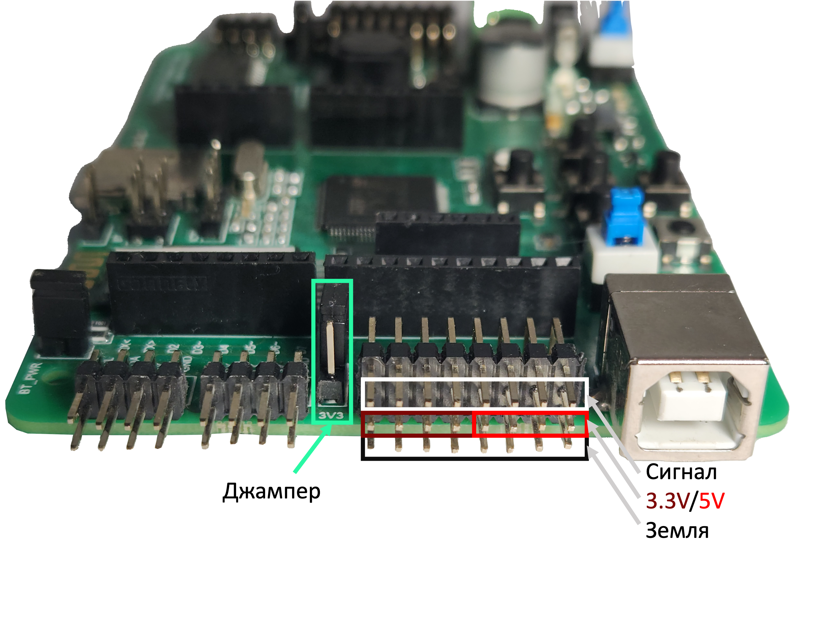
Maximum combined current for all IN ports: 500 mA. IN1–IN4 can be switched between 5 V and 3 V with a jumper; IN5–IN8 are fixed at 5 V.
OUT
The eight OUT ports are on the right side of the board. They are primarily for actuators, including servomotors; OUT1–OUT5 can generate hardware PWM. An OUT port can be configured as an input if needed, but none can be used as an analog input.
OUT connectors are vertical: bottom row is ground, middle row is power, and top row is signal.
Combined current for OUT ports is 500 mA or 3 A, depending on the jumper setting (see motor and servomotor power). OUT1–OUT4 can be switched between 5 V and 3 V; OUT5–OUT8 are fixed at 5 V. The combined current for 3 V-powered ports is limited to 500 mA regardless of the OUT power jumper.
Motor ports
The four DC motor ports are in the upper-right corner. Two L293DD motor drivers control them.
Motor connectors are vertical: bottom row is negative and top row is positive.
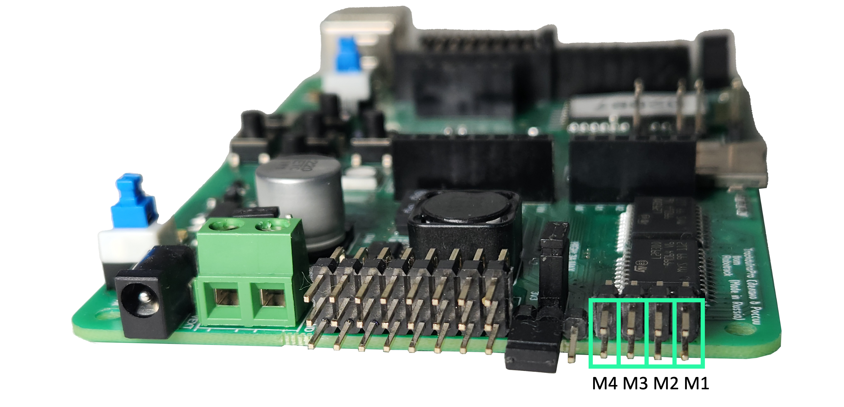
Maximum current per channel is 600 mA, or 1,200 mA briefly. Use the motor-control functions to control the drivers.
Arduino Uno interface
The Arduino Uno interface is in the center of the board under the case cover. It fully conforms to Arduino UNO R3 and supports Arduino-compatible shields, standard examples, and experiments designed for Arduino. Programs can access its ports just as they would on a standard Arduino Uno.
PWM, analog, and power port locations also conform to Arduino UNO R3. Port names are printed on the board.
Built-in devices
Trackduino has built-in devices that let programs and algorithms run without external devices. The programmable buttons and RGB LED are useful for debugging.
Buttons
Built-in buttons work like external buttons. Use blocks from the Built-in Buttons block group.
| Block and generated function | Description |
|---|---|
 bool buttonRead(int button) | Returns TRUE when the button is pressed. Argument int button: button identifier: BTN_UP, BTN_DOWN, BTN_LEFT, BTN_RIGHT, or BTN_CENTER (the corresponding button images are shown in the source). |
RGB LED
The built-in RGB LED can display the primary colors (red, green, blue) or their combinations. Its pins cannot generate hardware PWM, so arbitrary color mixing is not available. For experiments with color mixing, use the RGB LED on the color sensor, connected to any three PWM ports (OUT1–OUT5).
Software PWM can be generated for the built-in LED if needed, for example with the SoftPWM library.
To control the LED pins directly, use RGB_RED, RGB_GREEN, and RGB_BLUE. For example, digitalWrite(RGB_RED); lights the red channel. Running digitalWrite(RGB_RED); digitalWrite(RGB_BLUE); lights red and blue together, producing purple.
Use blocks from the Built-in RGB LED group:
| Block and generated function | Description |
|---|---|
 void buitItRGB(int color) | Lights the built-in LED with the selected color. Values: OFF/0, WHITE/1, RED/2, GREEN/3, BLUE/4, YELLOW/5, PURPLE/6, and AQUA/7. |
MicroSD card slot
The MicroSD card slot is at the top of the board and supports MicroSD cards.
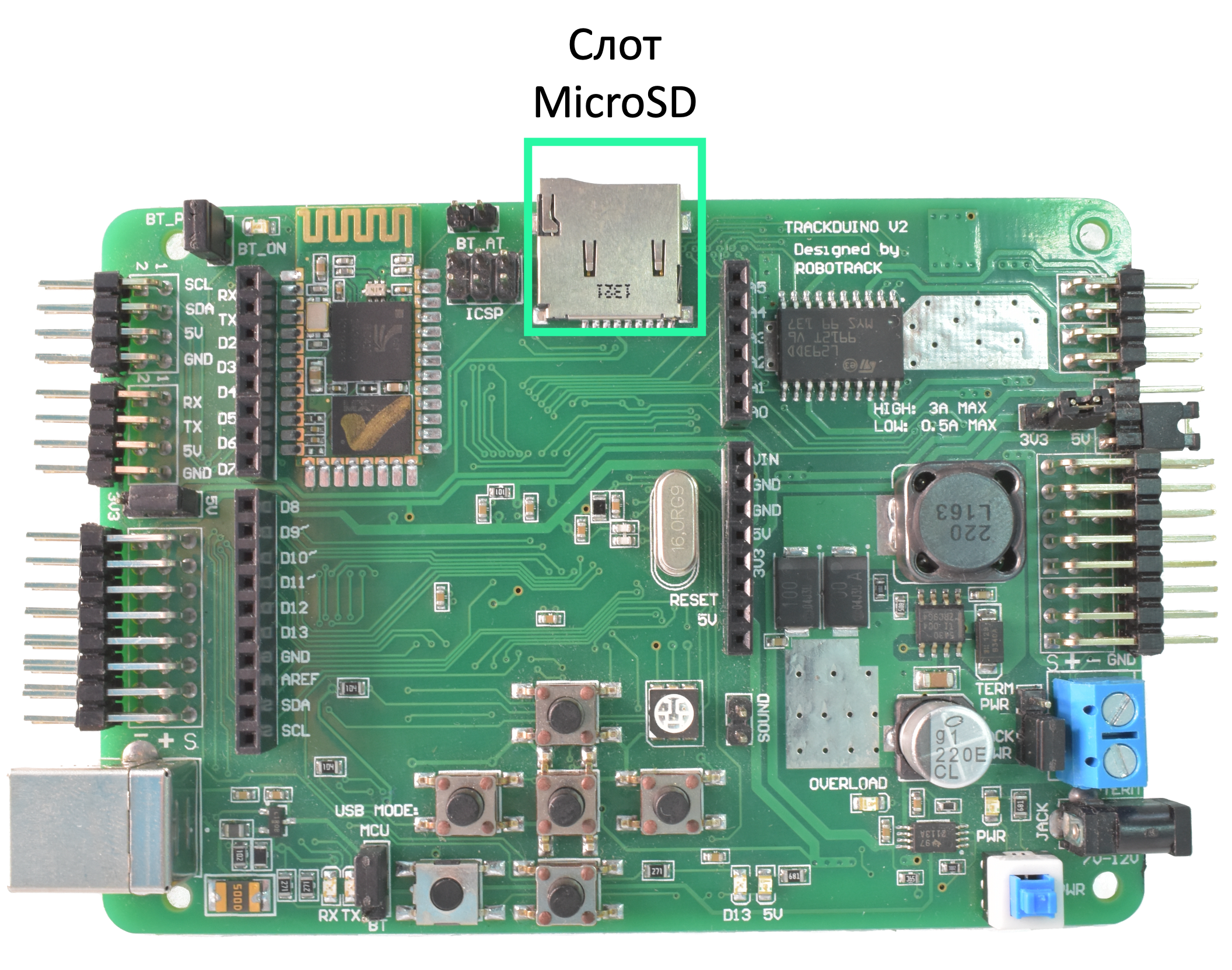
The card connects to the SPI bus (MISO, MOSI, CLK). Its chip-select (CS) pin connects to microcontroller port PB0, also addressable as Arduino port 53, SD_CS, or SS.
Use the SD library, included with Robotrack IDE. This library supports only cards formatted as FAT16 or FAT32.
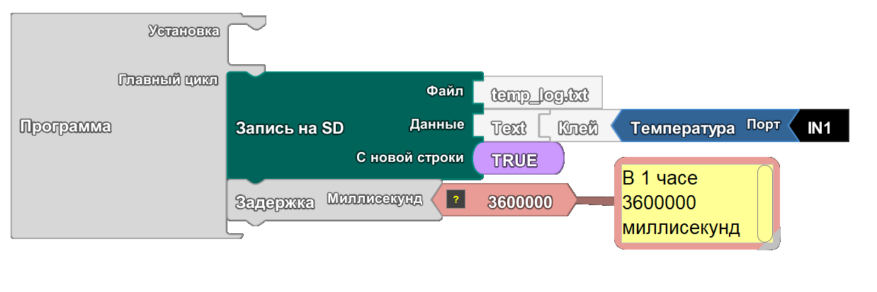
The visual environment currently supports writing data to a text file on the card. The block creates the named file if it does not exist and appends text, primarily for data logging. Its arguments are the file name relative to the card root, the text to write, and whether to add a newline.
Generated code:
#include <SPI.h>
#include <SD.h>
void setup()
{
  const int chipSelect = SD_CS;
  SD.begin(chipSelect);
}

void loop()
{
  File datafile = SD.open("file.txt", FILE_WRITE);
  if (datafile){
    datafile.print("Message");
    datafile.println("");
    datafile.close();
  }
}
Example project: an autonomous weather station that records temperature once per hour.
I2C
The I2C bus connectors are in the upper-left corner of the board.
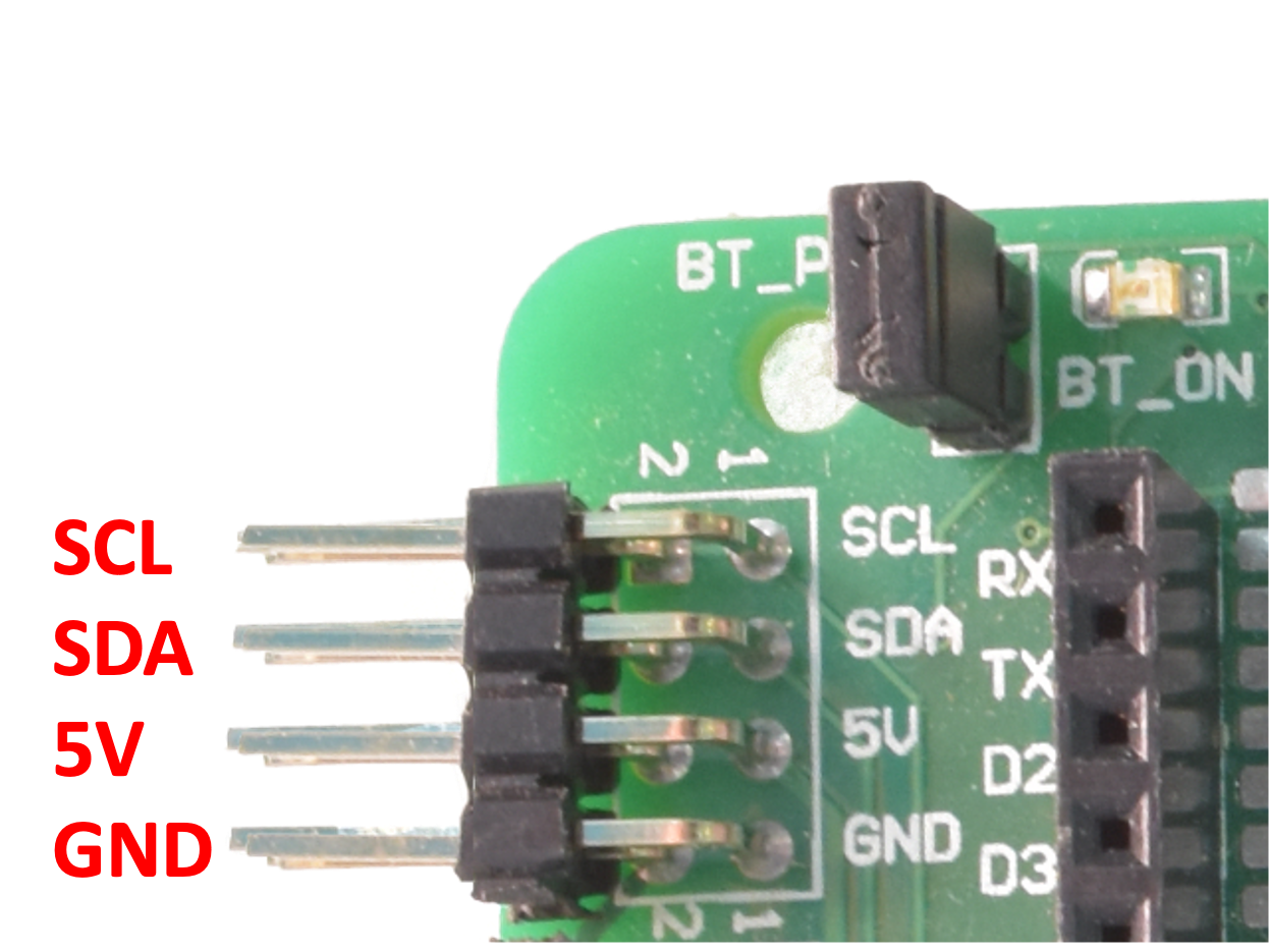
Two powered connectors are provided and connected in parallel. More than two devices can be connected using a custom splitter or breadboard. SCL and SDA are also connected to the Arduino connector in accordance with the R3 standard.
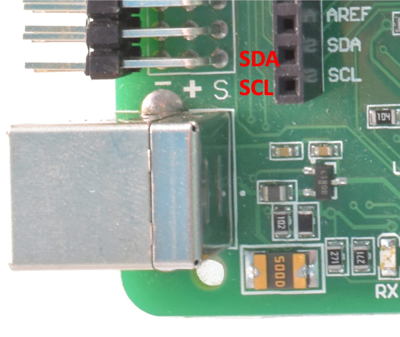
Robotrack kits connect the position sensor (gyroscope/accelerometer) to I2C.
Bluetooth
The HC-06 Bluetooth module is in the center of the board and communicates with the main microcontroller over UART0. It can also reset the microcontroller. Bluetooth can therefore be used for wireless UART data exchange, such as remote control, or to reflash the controller.
The module uses 115,200 baud. Each module has a unique name printed on its label.
Jumpers control the module:
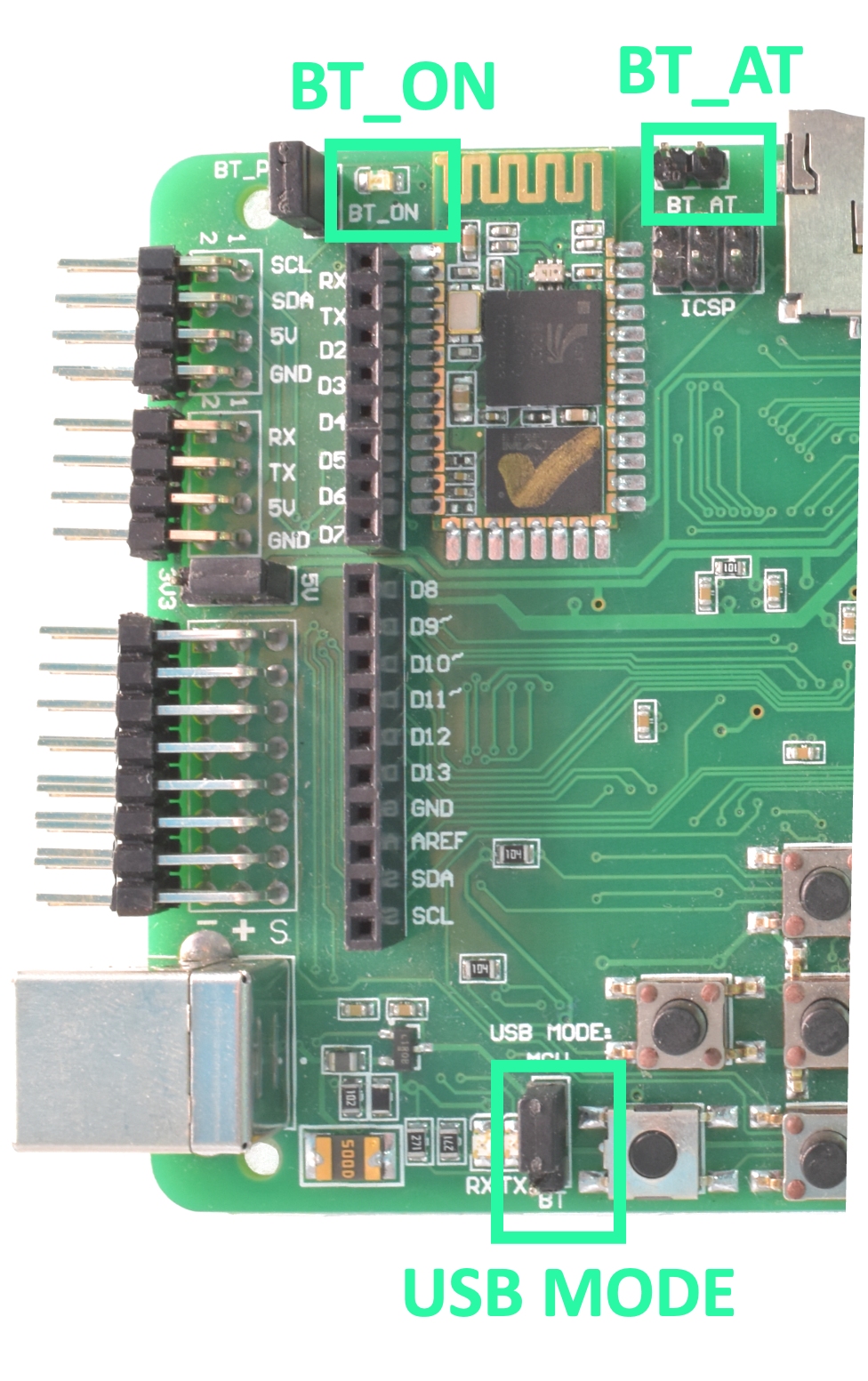
- BT_ON: switches module power. Open the jumper when the module is not in use to save power. You can also switch module power with
bluetoothON()andbluetoothOFF(); it is on by default. - BT_AT: close the jumper to configure the module with AT commands (advanced users).
- USB MODE: MCU/BT: in the lower position, connects the module TX/RX lines directly to USB so AT commands can be sent from a computer.
When USB power is detected, the Bluetooth module is automatically disconnected from UART0 data lines, but remains powered. This prevents signal conflicts and allows quick USB reprogramming while using Bluetooth PDU.
A status LED is next to the module: rapid flashing means ready to connect; nearly steady light with occasional flashes means connected. The default pairing password is 1234. Change it with AT commands if needed.
ICSP
The ICSP interface is for reflashing the main microcontroller with an in-circuit programmer, without using the bootloader. It is part of the Arduino interface and has the same position and pinout as Arduino UNO R3.
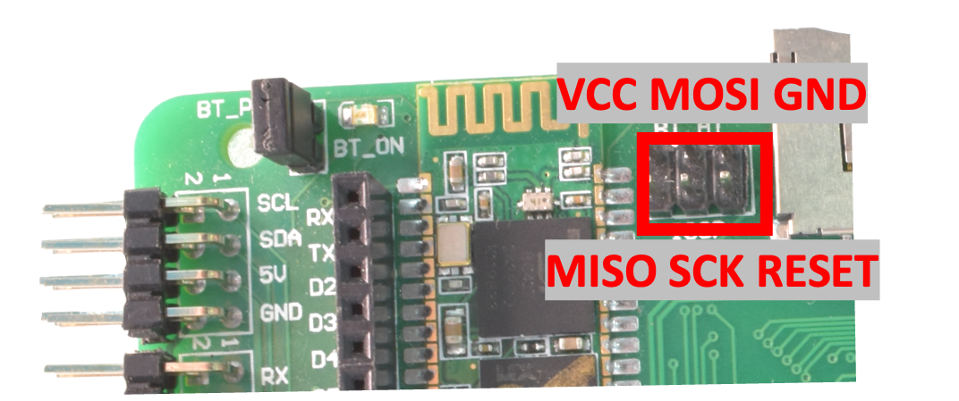
Incorrect programming can permanently damage the microcontroller. Use a programmer only if you know exactly what you are doing and why.