
Trackduino Pro is a multifunctional controller built around an STM32 microcontroller. It can be reprogrammed in two environments: MicroPython and Arduino C. The controller is the core of a robotics kit. It collects and digitizes signals from external digital and analog sensors, processes them according to a user program, controls digital and analog actuators, communicates with other devices over wired and wireless digital interfaces, and controls four DC motors rated from 6 to 12 V.
Trackduino Pro specifications
- Connects to a computer via USB or Bluetooth.
- Built-in Bluetooth supports sending and receiving data and flashing the microcontroller.
- Five programmable buttons, each connected to its own I/O port; together with the RGB LED, they provide a basic human-machine interface without external devices.
- microSD card slot for expanding non-volatile storage.
- Supply: 7–12 V. Two connectors: a jack for battery packs and a screw terminal for 6–18 V sources.
- Eight powered input ports (GND–Vin–S), each with ADC; ports 1–4 support interrupts; selectable 5 V/3 V supply.
- Eight powered output ports; ports 1–5 provide hardware PWM for third-party chips; selectable 5 V/3 V supply.
- Four DC motor ports driven by two L293 drivers with overcurrent protection. Each channel uses two output ports for direction and braking and an additional PWM port for speed.
- Standard Arduino UNO R3 interface, independent of the other I/O ports; adds 24 I/O connections for shields and libraries.
- RGB LED can display approximately 16 million colors for visual indication of events and parameters.
- Two exposed USART ports with power (RX, TX, 5 V, GND).
- Two exposed I2C ports with power (SCL, SDA, 5 V, GND).
- BOOT mode switch: RUN and DFU.
- STM32F407 processor with 1 MB flash:
- 32-bit Cortex-M4F microcontroller with floating-point DSP; up to 82 I/O pins.
- Clock speed up to 168 MHz; 1 MB Flash, 196 KB RAM, and 4 KB backup SRAM (EEPROM equivalent).
- DSP and floating-point support.
- 16-bit timers: 2 basic, 8 general-purpose, 2 advanced, and 2 watchdog; plus two 32-bit general-purpose timers.
- USB 2.0 full-speed device/host/OTG with on-chip PHY; high-speed/full-speed USB with separate DMA, full-speed PHY, and ULPI support.
- 10/100 Ethernet MAC with separate DMA and IEEE 1588v2, MII/RMII PHY interfaces.
- Three SPI interfaces (37.5 Mbit/s), two multiplexed with full-duplex I2S.
- Three I2C interfaces with SMBus/PMBus; four USART and two UART interfaces up to 10.5 Mbit/s, with ISO 7816, LIN, IrDA, and modem control.
- Two CAN 2.0B Active interfaces; SDIO for SD cards.
- DCMI 8–14-bit parallel camera interface (up to 54 MB/s); analog random-number generator; CRC unit.
- RTC; three 12-bit ADCs (2.4 million samples/s, 16 channels, up to 7.2 million samples/s in triple-interleaved mode); two 12-bit DACs.
- 16-channel DMA with FIFO and burst-transfer support; parallel LCD interface (8080/6800); FSMC for CompactFlash, SRAM, PSRAM, NOR, and NAND.
- JTAG or SW debugging; operating temperature: −45 to +85 °C.
Trackduino Pro platform features
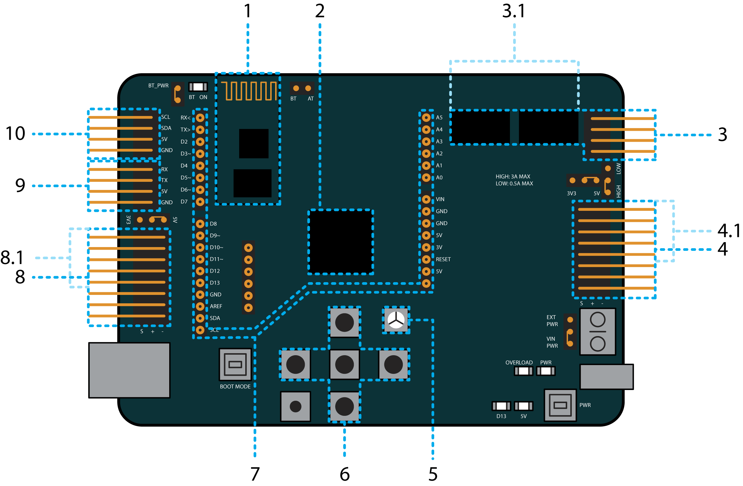
The diagram identifies: 1 — built-in Bluetooth; 2 — STM32F407VGT6 microcontroller; 3 — MicroSD slot; 4 — four DC motor ports (4.1 — two dual-motor drivers); 5 — eight output ports (5.1 — five PWM outputs); 6 — built-in RGB LED; 7 — five built-in control buttons; 8 — Arduino Uno interface; 9 — eight input ports (9.1 — five PWM-capable inputs); 10 — two exposed USART ports; 11 — two exposed I2C ports.
Trackduino Pro version for Python
The Trackduino Pro Python firmware includes a built-in MicroPython interpreter.
MicroPython is an implementation of Python 3 that includes most of the core Python standard library subset and is optimized for microcontrollers. The Trackduino Pro MicroPython version is based on MicroPython for Pyboard. See the official documentation.
To program the platform in Python, install the driver (Windows 10 installs it automatically). After the driver is installed and the platform is connected in the correct mode, it appears on the computer as a removable drive named PYBFLASH.
Instructions and the latest MicroPython updates are available on the GitHub portal.
Trackduino Pro version for C++ (Arduino C)
To program Trackduino Pro in C++ (Arduino C), set the board to DFU (Device Firmware Update) mode and install STM32CubeProgrammer. After installation, the board appears as a DFU device with an assigned COM port.
Robotrack IDE support for Trackduino Pro is under development, according to the source article.
Power
The board can be powered by USB or an external source. External power connects through the Jack connector or the screw terminal (TERM). When multiple sources are connected, USB/external switching is automatic; switching between the jack and terminal is manual with jumper XP13.
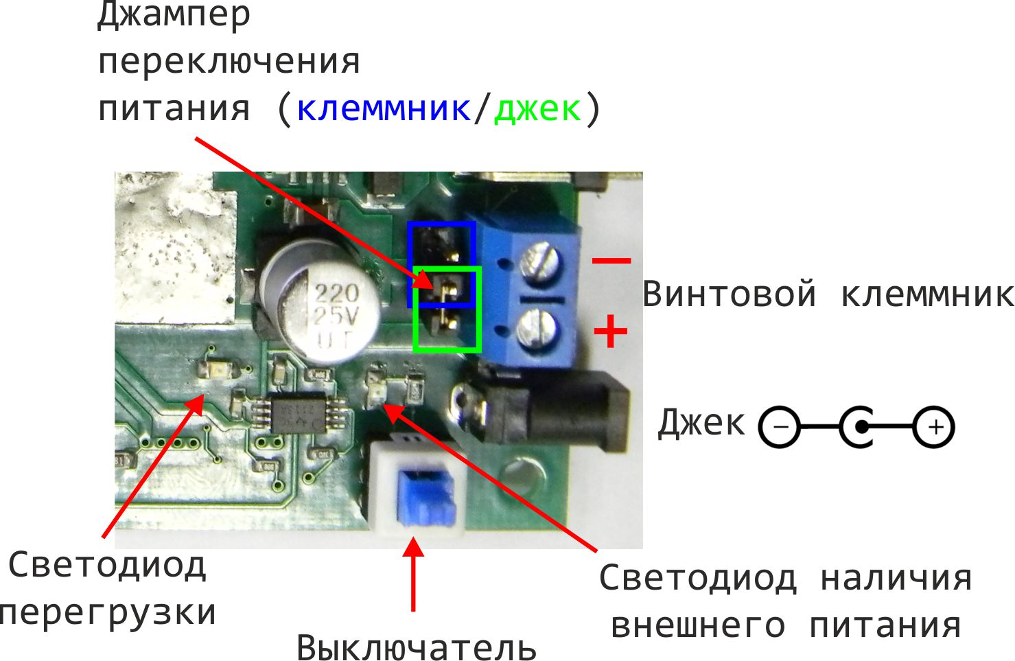
Power requirements: USB: exactly 5 V. External power: 6–12 V. Sources may include a 9 V battery holder with six AA cells, Li-ion batteries with a combined voltage no higher than 12 V, or a 6–12 V DC supply rated for at least 500 mA (1–3 A with several motors and servomotors).
Weak sources (for example, alkaline or NiMH batteries and low-power adapters) may experience voltage drops under heavy loads, resetting the controller. Heavy loads include abruptly stopping or stalling motors, reversing motors before they stop, connecting many servomotors, or using servomotors to lift excessive loads.
Motor power comes directly from the external source without voltage reduction. Do not exceed motor voltage limits. Robotrack kit motors are rated for a maximum of 9 V.
USB power is recommended for projects without high-current devices such as motors and servomotors. External power is required for projects using motors or more than two servomotors.
Motor and servomotor power: Motor-driver power comes directly from the external source; motors cannot run from USB. OUT ports, including those used for servomotors, are powered through a regulator rated up to 500 mA. This is sufficient for external devices and one or two servomotors. If more than two servomotors exceed that current, the OUT overload LED lights. Use external power and set jumper XP9 to HIGH to provide up to 3 A to 5 V OUT ports.
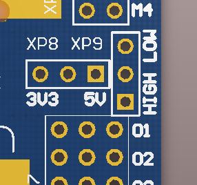
Important: At HIGH, OUT ports are powered only from the external source and are unpowered when using USB. Set the jumper to LOW to power OUT ports from USB.
Power button: with external power only, it switches the whole device; with USB only, it has no effect (motor drivers are unpowered); with both sources, it switches power to the motor drivers only, allowing USB programming without the motors starting unexpectedly.
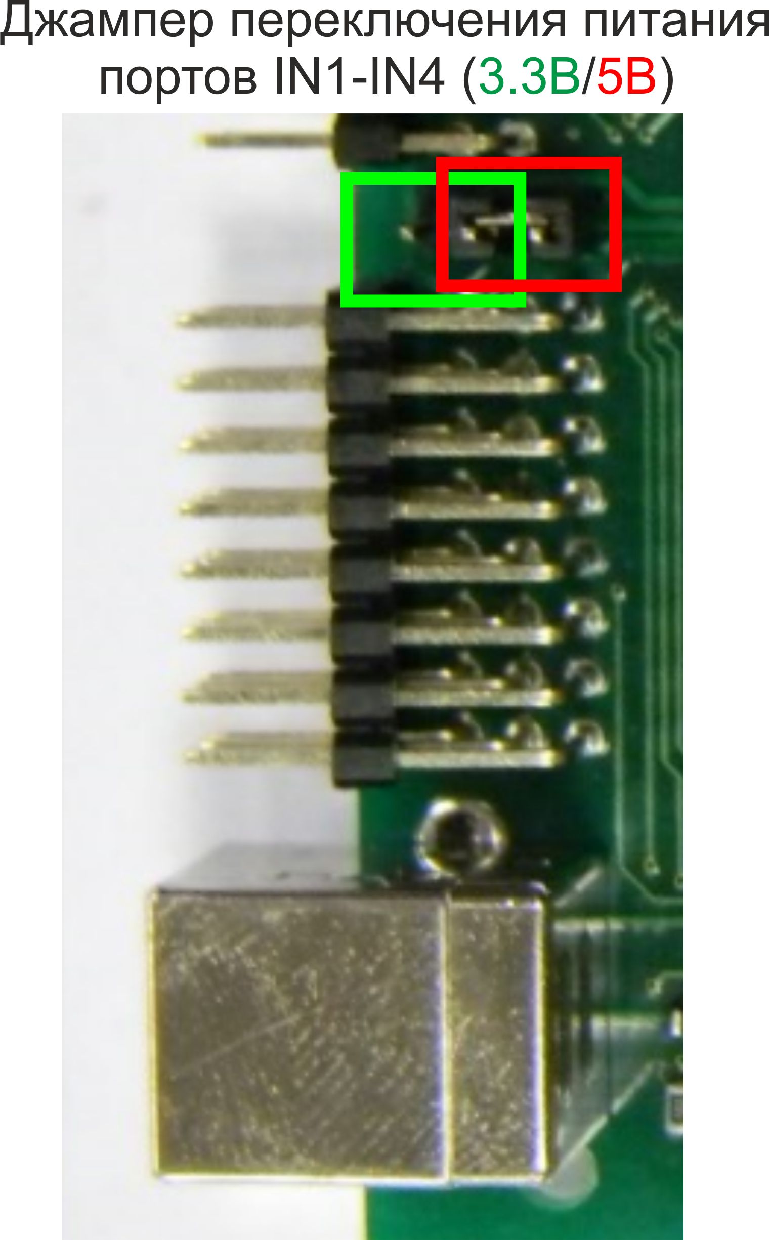
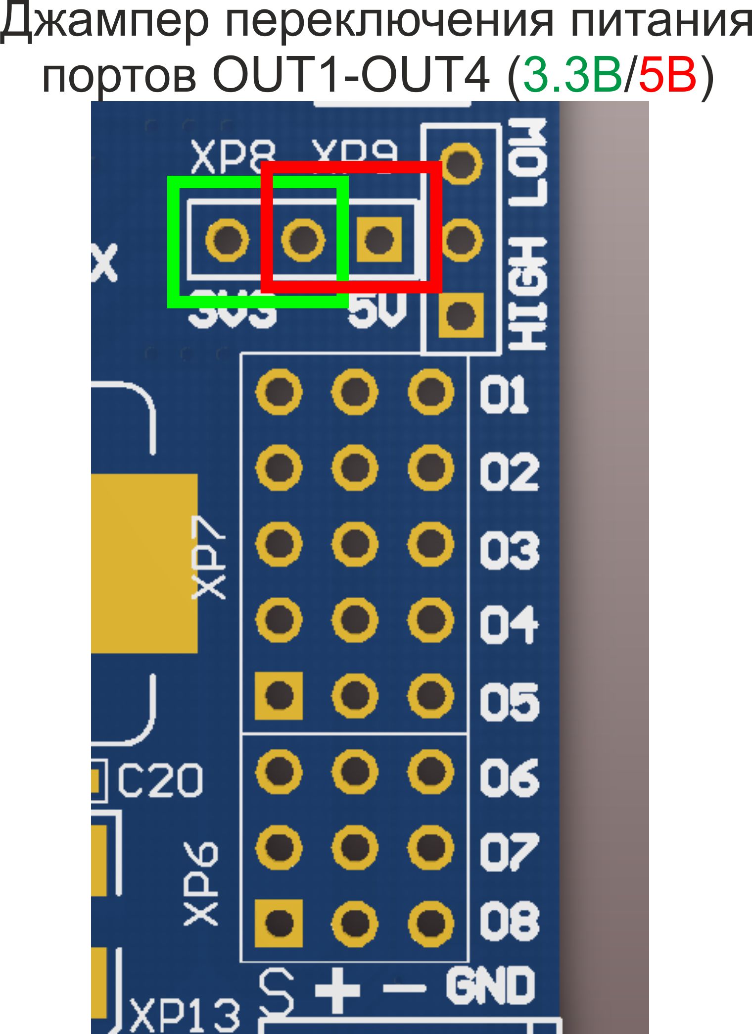
Switching between 3 V and 5 V: IN1–IN4 and OUT1–OUT4 can be switched with jumpers located above IN1 and OUT1. This is useful for third-party 3 V sensors. The default is 5 V; remove the case cover to access the jumpers. Robotrack kit electronics operate at 5 V.
Ports
Trackduino Pro has many external-device ports. IN and OUT ports are independent of other ports, including the Arduino Uno interface.
IN ports
Eight IN ports are on the left side of the board, primarily for sensors. They are analog inputs connected to an ADC and can measure voltage. Any can be configured as an output for a simple actuator; IN1–IN5 can generate hardware PWM.
Connect vertically: bottom row is ground, middle row is power, top row is signal.
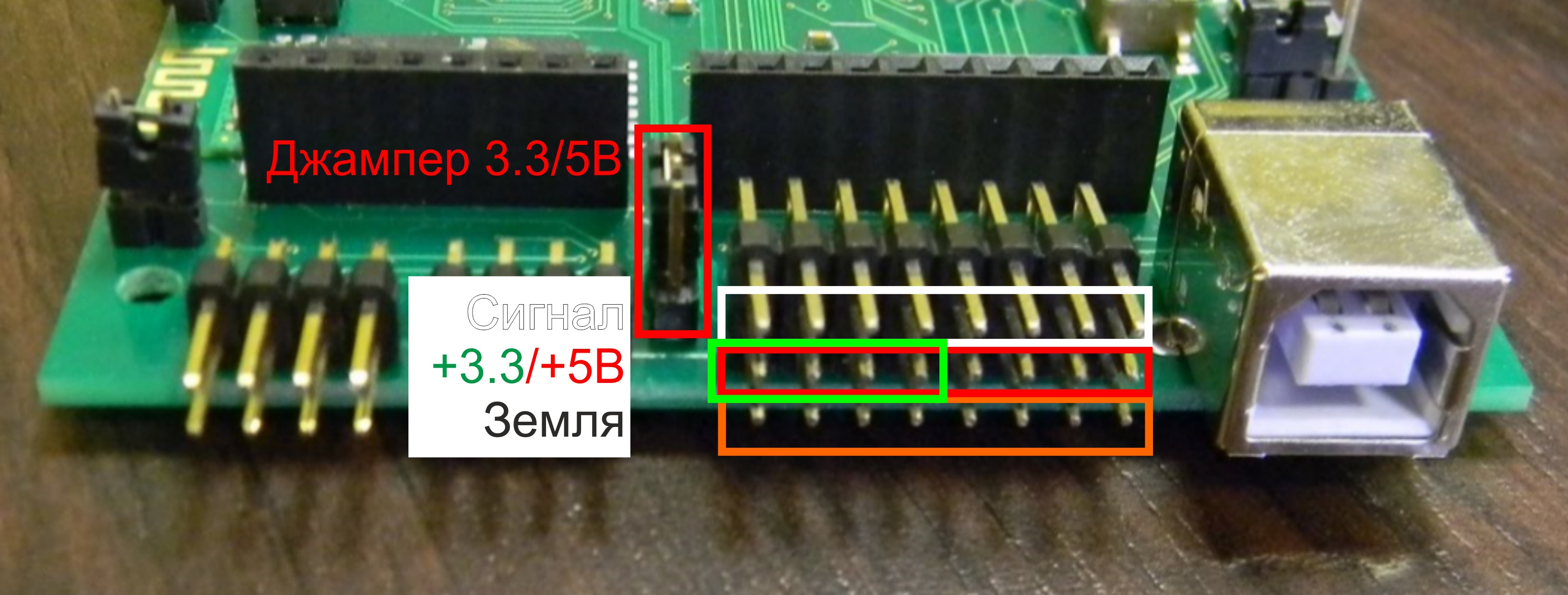
Maximum combined IN current: 500 mA. IN1–IN4 can be switched between 5 V and 3 V; IN5–IN8 are fixed at 5 V.
Motor ports
Four DC motor ports are in the upper-right corner and are controlled by two L293DD drivers. Connect vertically: bottom row is negative and top row is positive.
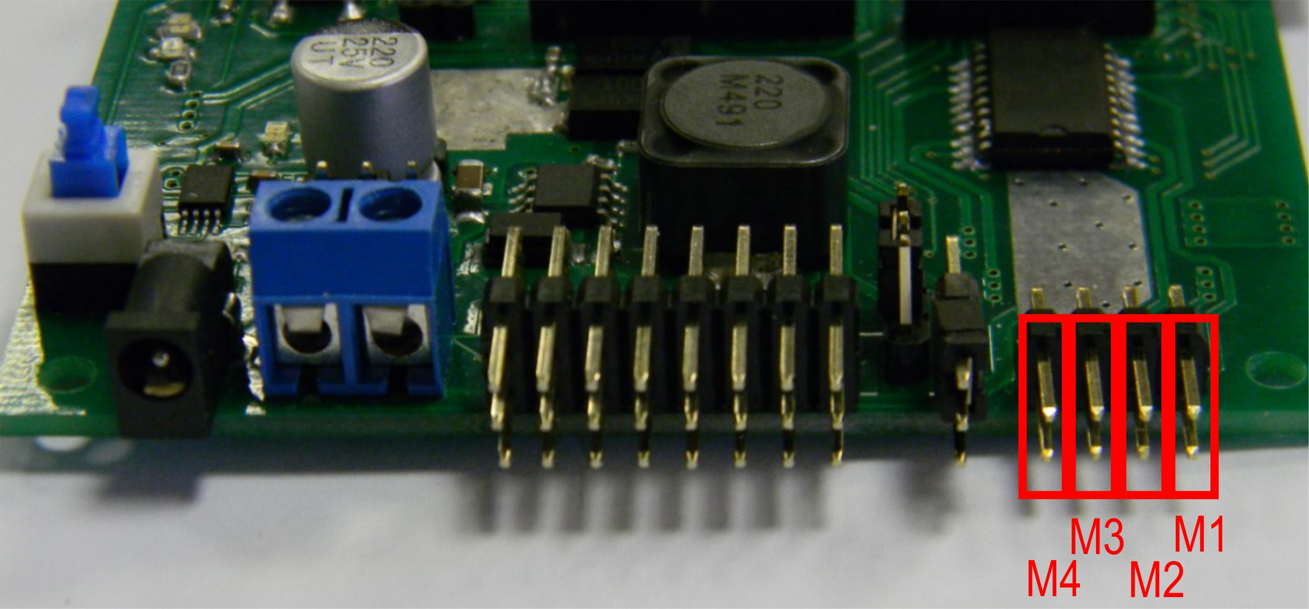
Maximum current per channel is 600 mA, or 1,200 mA briefly. Driver operating voltage range: 4.5–36 V.
Arduino Uno interface
The Arduino Uno interface is in the center of the board under the case cover. It conforms to Arduino UNO R3 and supports compatible shields, standard examples, and Arduino experiments. Programs can access these ports as they would on a standard Arduino Uno. PWM, analog, and power port positions also conform to UNO R3; port names are printed on the board.
Built-in devices
Trackduino Pro has built-in devices for running programs and algorithms without external hardware. Its programmable buttons and RGB LED are useful for debugging. The BOOT/RUN switch selects firmware-update mode or normal operation and is relevant when flashing the board for Arduino C.
Interfaces
UART
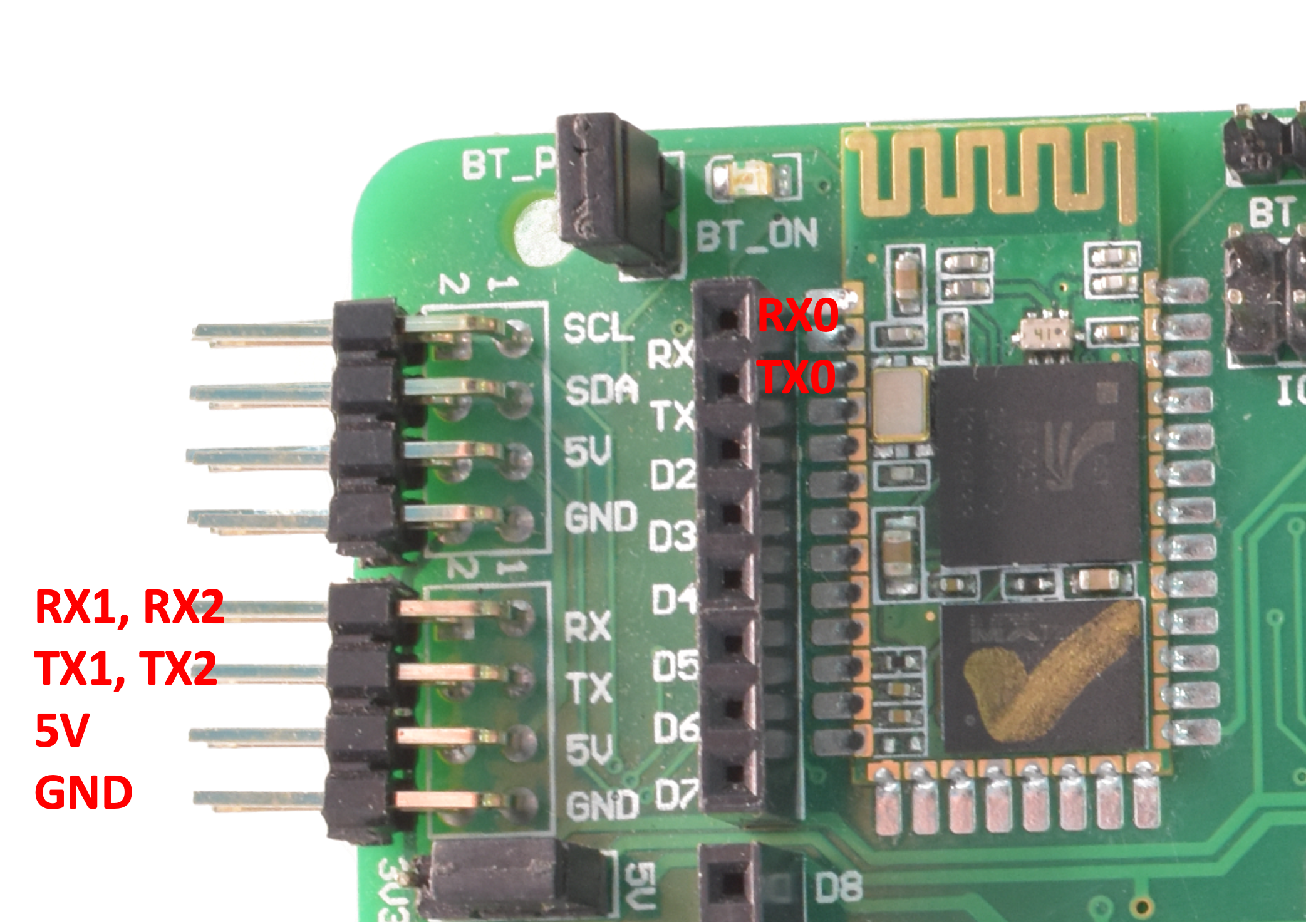
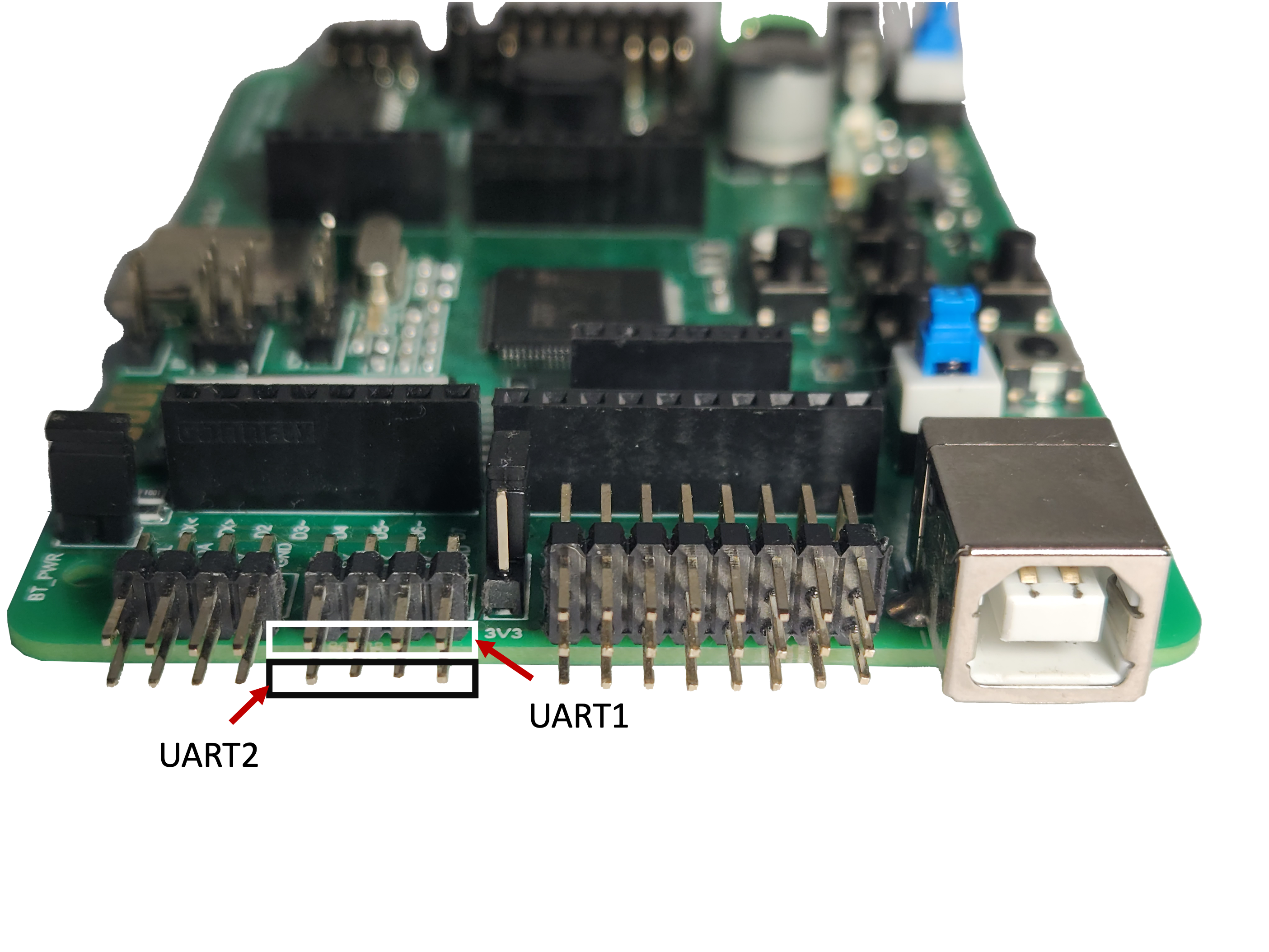
The controller has four independent hardware USART interfaces:
- UART0: main interface connected to the controller’s USB port.
- UART1 and UART2: exposed on the left side with 5 V power, available for user devices. Robotrack kits connect a display and Audiotrack to these ports.
- UART3: main interface connected to the Bluetooth module.
I2C
The I2C bus connectors are in the upper-left corner of the board.
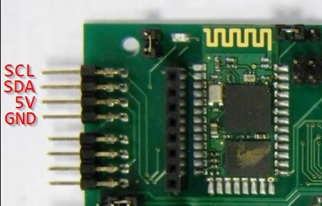
Two powered connectors are provided and connected in parallel. More devices can be attached through a custom splitter or breadboard. SCL and SDA are also exposed on the Arduino connector in accordance with R3.
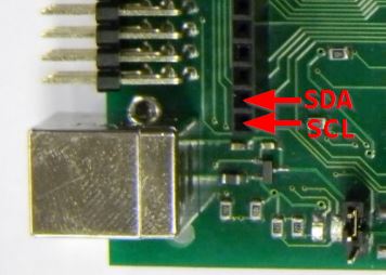
Robotrack kits connect the position sensor (gyroscope/accelerometer) to I2C.
Bluetooth
The HC-05 Bluetooth module is in the center of the board and communicates with the main microcontroller over UART4. It can also reset the microcontroller, so Bluetooth can be used for wireless UART data exchange (for example, remote control) or for reflashing the controller.
The module uses 115,200 baud and has a unique name. An external programmer is required to configure it. Unlike the Trackduino controller, this Bluetooth module does not depend on a USB connection.
Its status LED flashes rapidly when ready to connect and stays almost continuously lit, with occasional flashes, when connected. The default pairing password is 1234; it can be changed with AT commands.
ICSP
ICSP is used to reflash the main microcontroller with an in-circuit programmer without using the bootloader. It is part of the Arduino interface and has the same position and pinout as Arduino UNO R3.
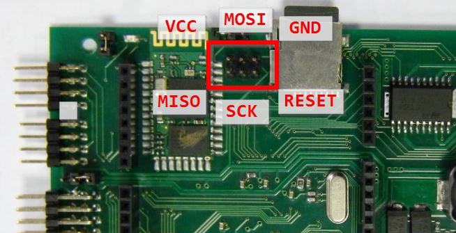
Incorrect flashing can permanently damage the microcontroller. Use a programmer only if you know exactly what you are doing and why.