
This article walks you through the basic steps for getting started with a Robotrack construction kit. It briefly explains how to:
- Download software for creating programs and uploading them to the controller.
- Open, edit, and upload programs.
- Connect external devices to the controller correctly.
- Use ready-made program templates (algorithms).
For more detailed information about the software and sensors, see the full articles linked from the Wiki home page.
Downloading and installing the software
Robotrack IDE is used to create, edit, and upload programs to the controller.
- Open https://yadi.sk/d/Z4f47hEixEy7g in a web browser.
- Click Download.
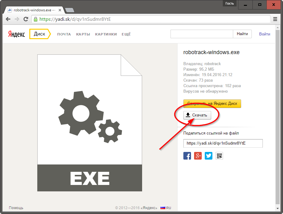
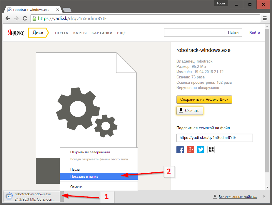
- Wait for the download to finish and open the folder containing the downloaded file.
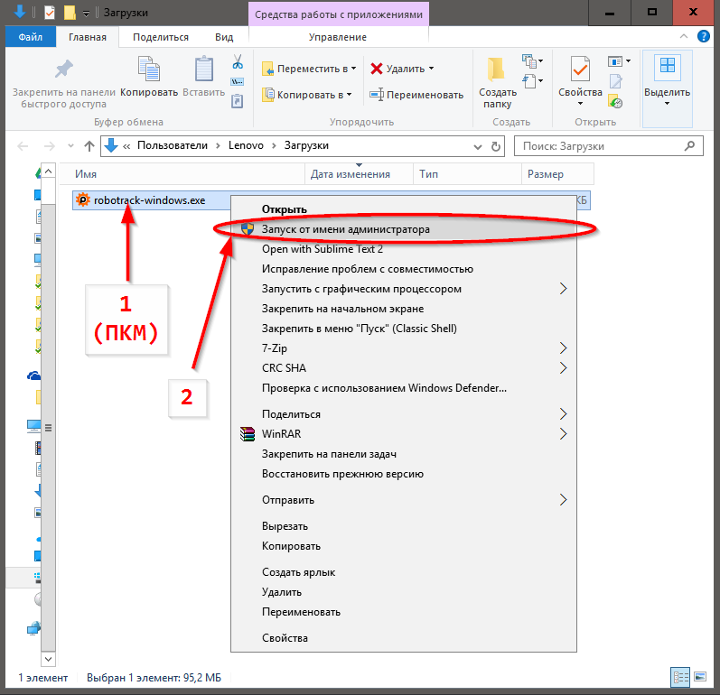
- Right-click the file and select Run as administrator.
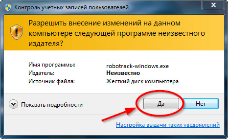
For Windows 7, click Yes in the User Account Control prompt.
For Windows 8 or 10, if a warning says the app is from an unknown source, click More info to show additional launch options.
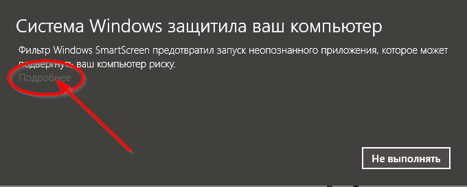
Click Run anyway.
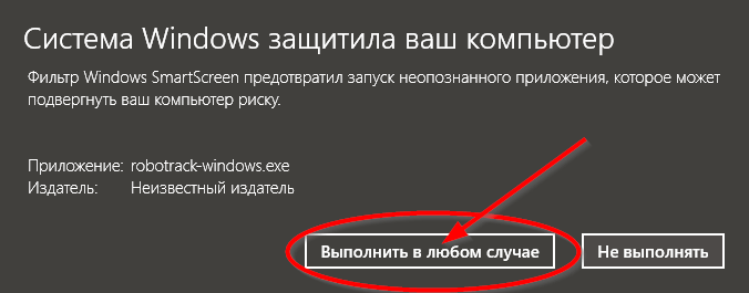
If either system asks for an administrator password, contact your system administrator.
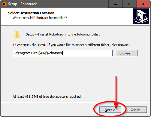
- The setup wizard opens. On its first screen, choose the installation folder; keeping the default path is recommended. Click Next.
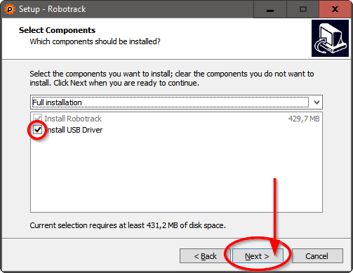
- Make sure Install USB driver is checked, then click Next.
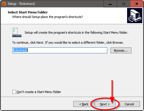
- Choose a name for the program folder in the Start menu. Keep the defaults and click Next.
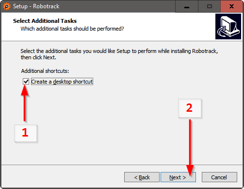
- Check Create a desktop shortcut if you want a desktop shortcut (recommended), then click Next.
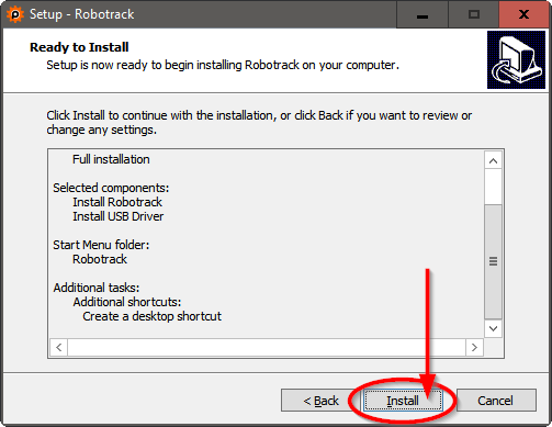
- Click Install.
- Wait for installation to finish. Clear Launch Robotrack if you do not want to start the program immediately (recommended), then click Finish.
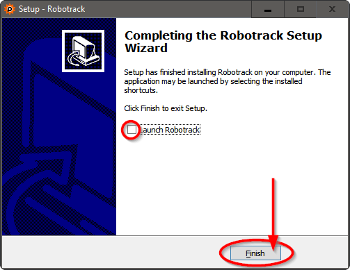
- Robotrack IDE is installed. Use the desktop shortcut to launch it later.
It is recommended to launch the program only after connecting the controller to the computer.
Connecting the controller to a computer
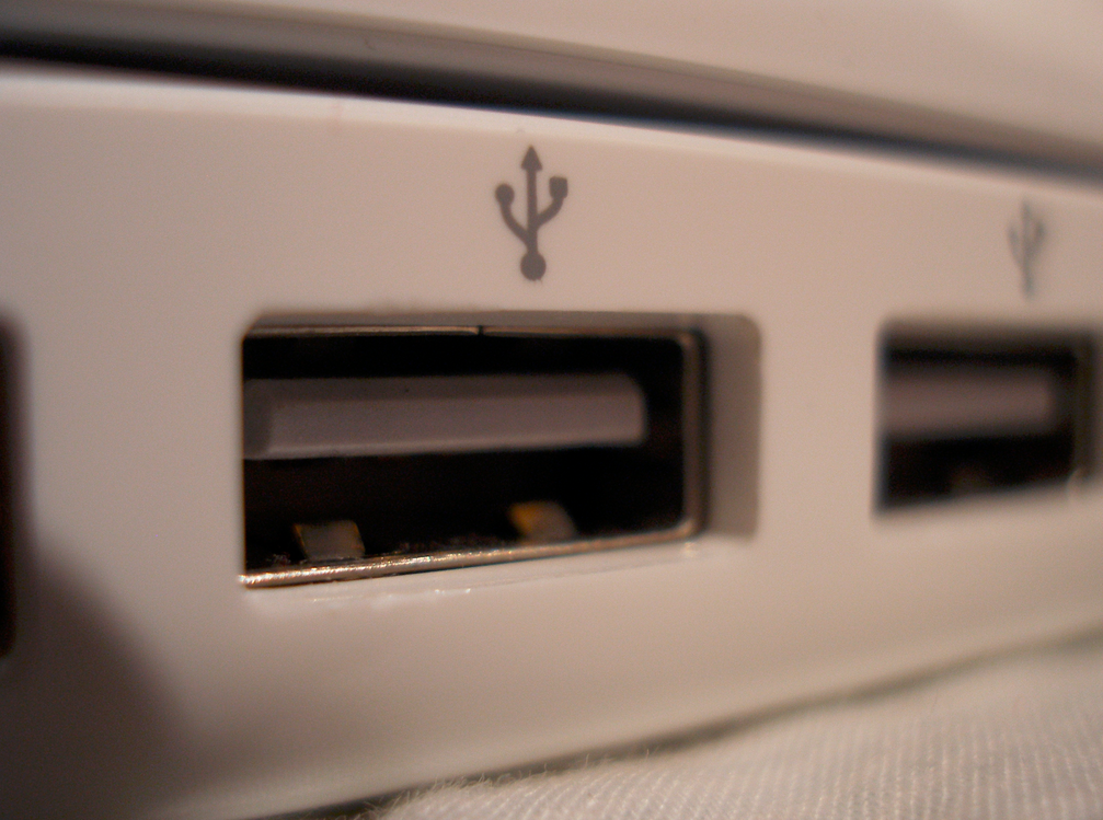
The controller connects through a USB port, the type commonly used for flash drives. Find a free USB port on the computer.
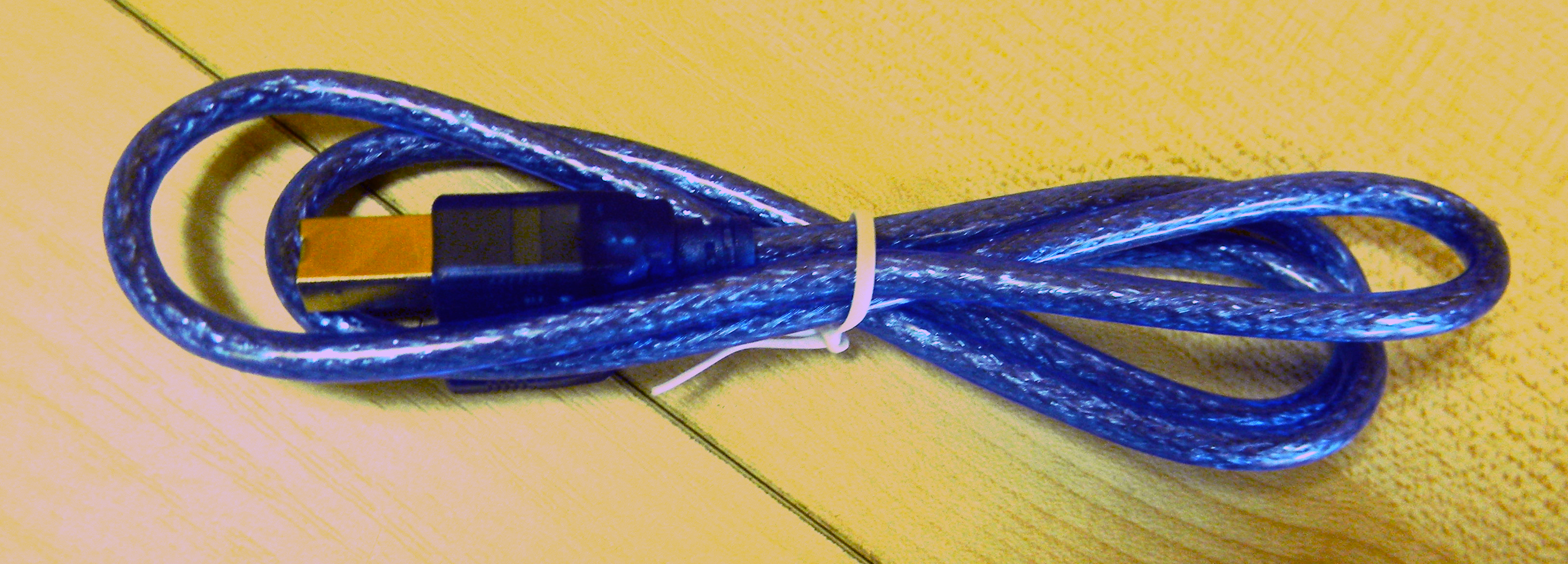
Take the USB cable from the kit.
Find the USB connector on the board.
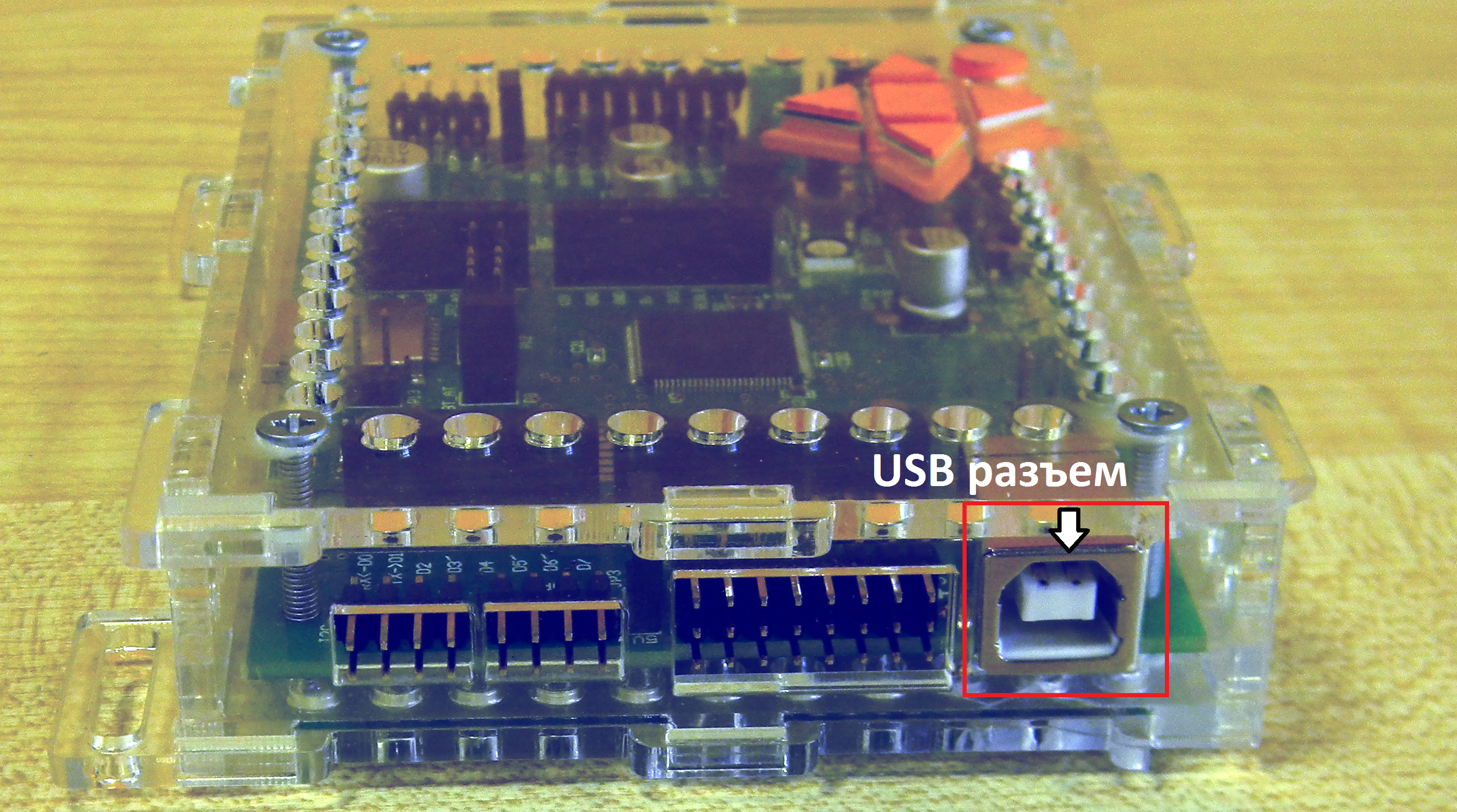
Connect the cable to the controller and to a free USB port on the computer.
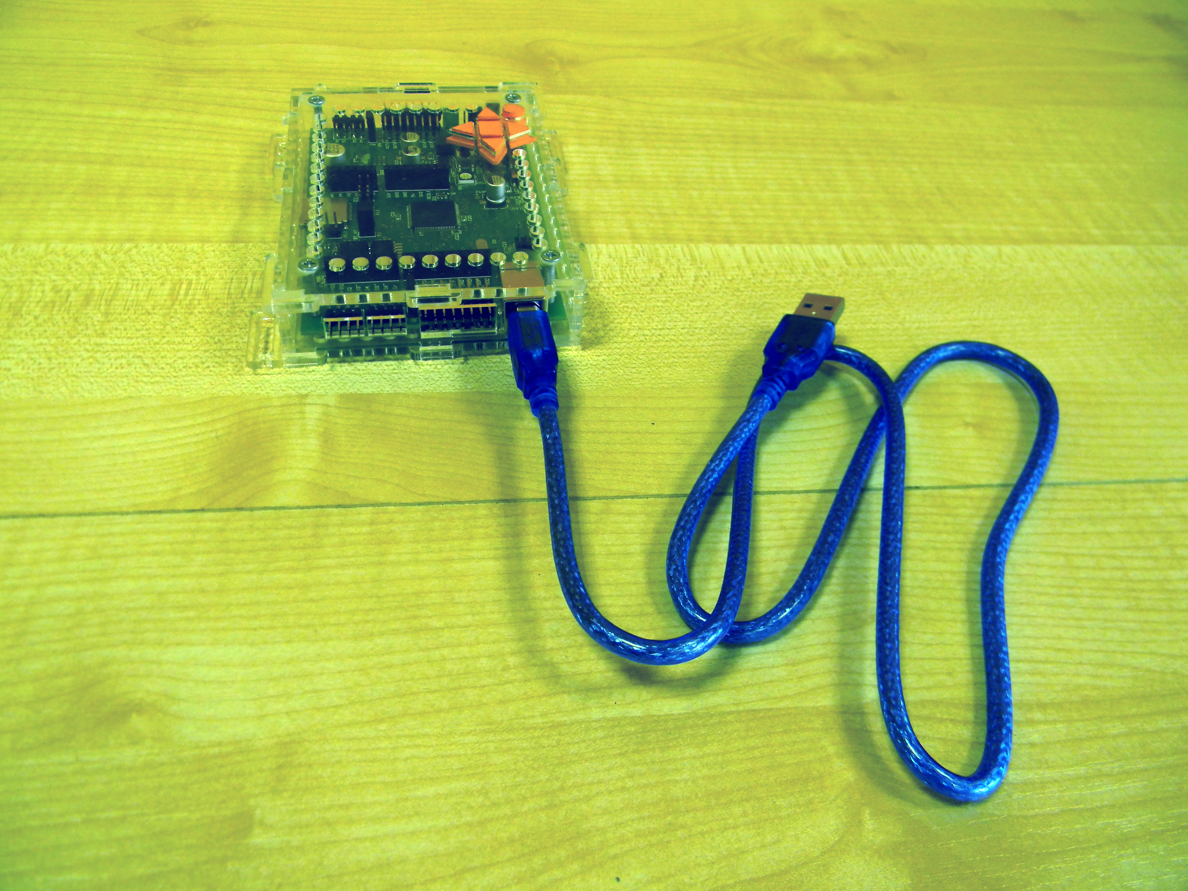
You do not need to press any buttons on the controller. The power button does not affect the controller while it is connected to USB. Batteries are optional. If you have already assembled a model and installed batteries, you may leave them in, but it is recommended to switch off battery power to prevent motors from starting when a program finishes uploading.
When connected for the first time, the computer automatically installs drivers. This usually takes less than a minute. A notification then identifies the device as Serial Interface (COMx), where x is usually a number from 1 to 10. Remember this COM port number.
If you missed the notification, find the port in Control Panel:
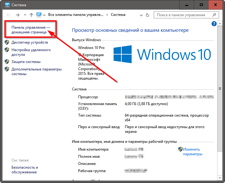
- Open Control Panel from the Start menu, or right-click My Computer, select Properties, and open the Control Panel home page.
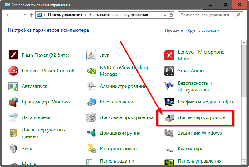
- Double-click Device Manager.
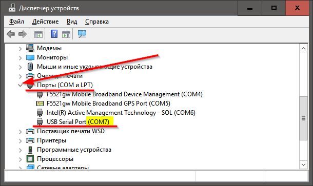
- Expand Ports (COM & LPT) and find USB Serial Port or USB Serial Port (localized). The assigned port is shown in parentheses after the device name. For example, the port in the image is COM7.
When disconnected, the controller disappears from Device Manager. It usually gets the same port when reconnected, but the assignment can change after a computer restart. Check the port if program uploads fail.
Launching the program
- Double-click the Robotrack desktop shortcut.
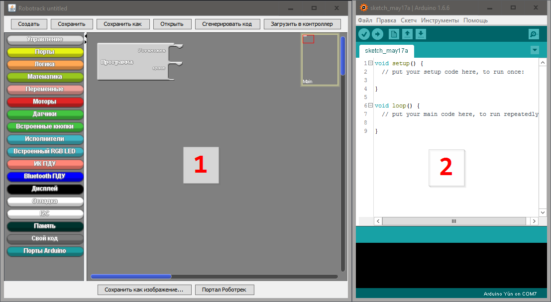
Two program windows open: the visual (block-based) environment and the text environment.
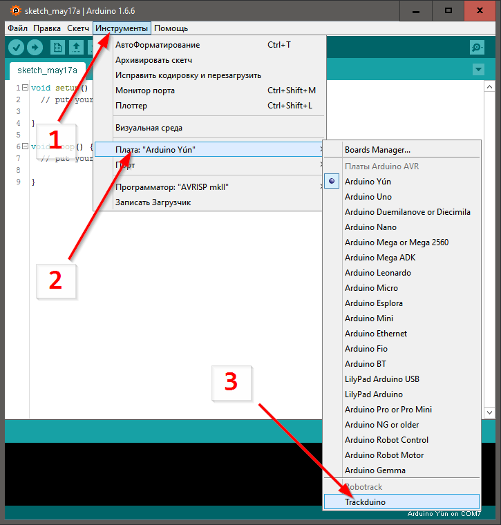
The first time you run the program, set up the text environment:
- Select Tools → Board → Trackduino. This is needed only once, unless you also use other Arduino controllers.
- Select Tools → Port and choose the COM port assigned to your controller. See how to find the port.
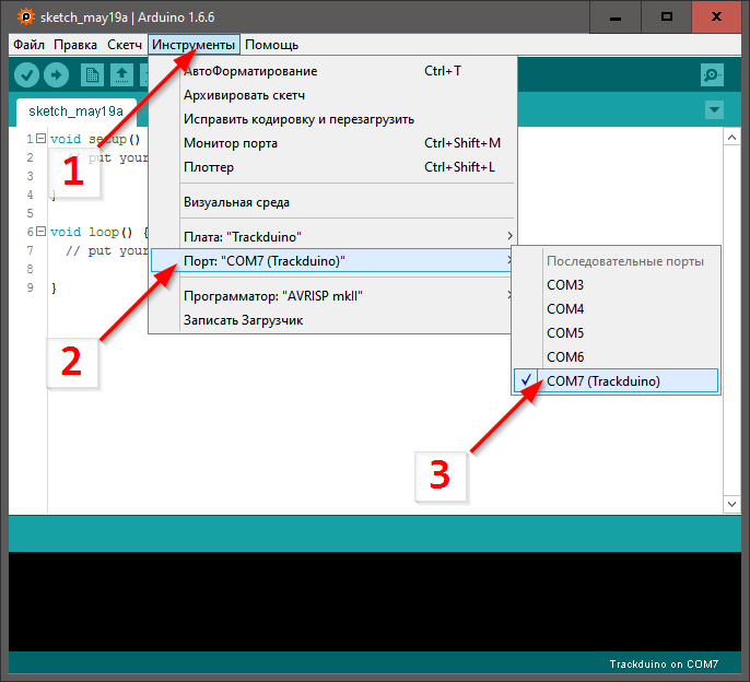
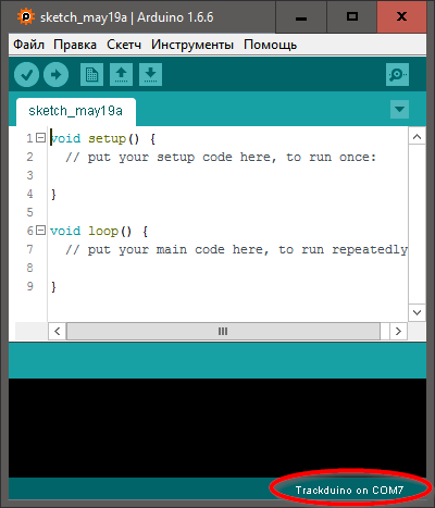
It is recommended to check the port after every launch. Confirm that the lower-right corner of the text window says Trackduino on COMx, with the correct port number.
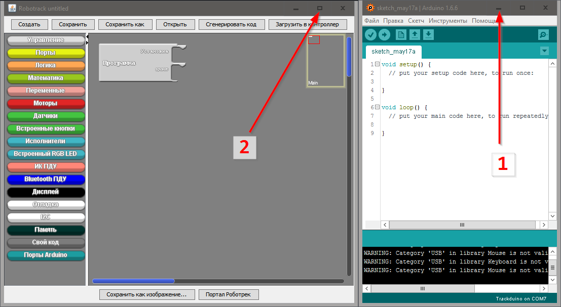
If you are not using text programs, minimize the text environment and maximize the visual environment: first minimize the text window, then maximize the visual window.
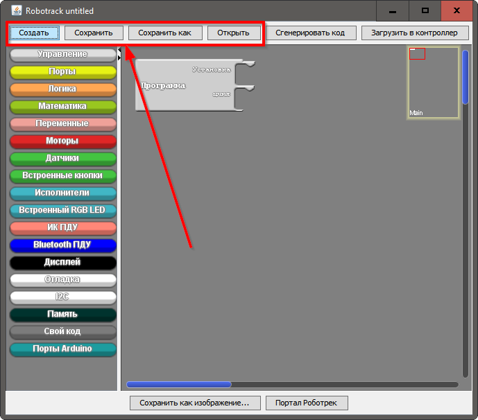
The visual environment opens with an empty program. You can create a program from scratch or start with an example. Use its toolbar buttons to create, open, and save visual programs.
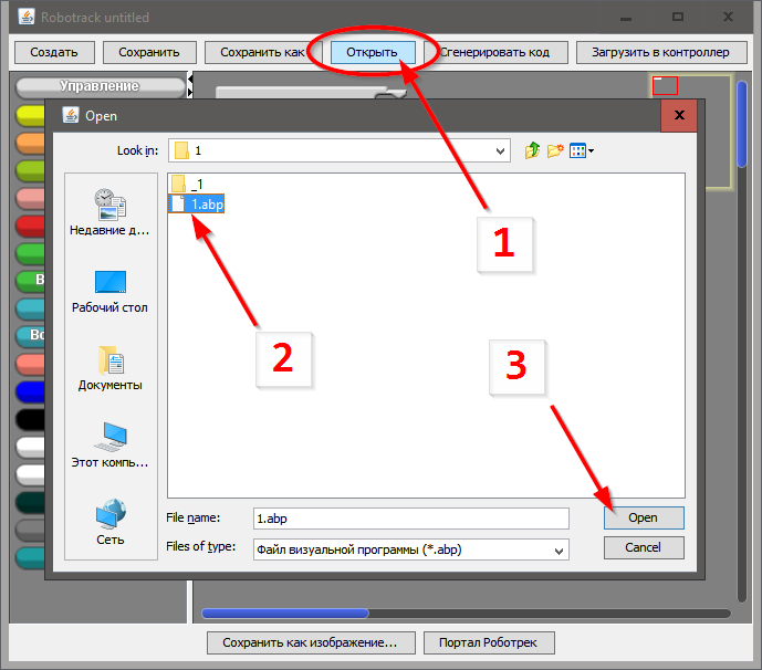
Opening an existing program
Click Open (1). In the file browser, select the required visual program with the .abp extension (2) and click Open (3). You can use one of the ready-made algorithms mentioned at the end of this article.
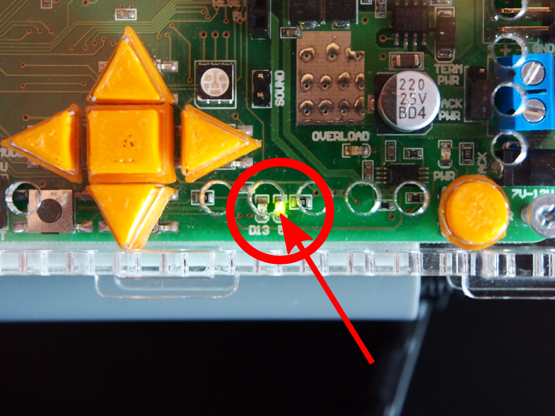
The program is ready to upload. Before uploading, make sure the controller is connected and its green 5V LED is on.
Editing programs
You can—and should—modify and extend the supplied example algorithms. See working with the visual environment to learn how to add blocks.
Uploading programs to the board
Models and their sensors are usually assembled before programming the controller. External devices and motors can remain connected while programming. The uploaded program starts automatically as soon as uploading finishes, so devices on IN and OUT ports may activate while the controller is still connected to the computer and the robot may move.
When ready, click Upload to controller on the visual-environment toolbar.
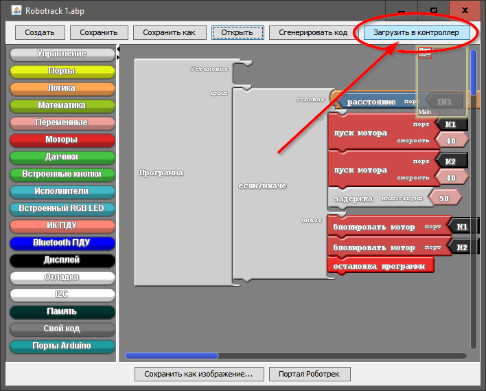
The text environment comes to the foreground with code generated from the visual program, and a save dialog appears. Each time you upload a new program, the software asks you to save the generated text program. Choose a folder; keeping the defaults and clicking Save is recommended.
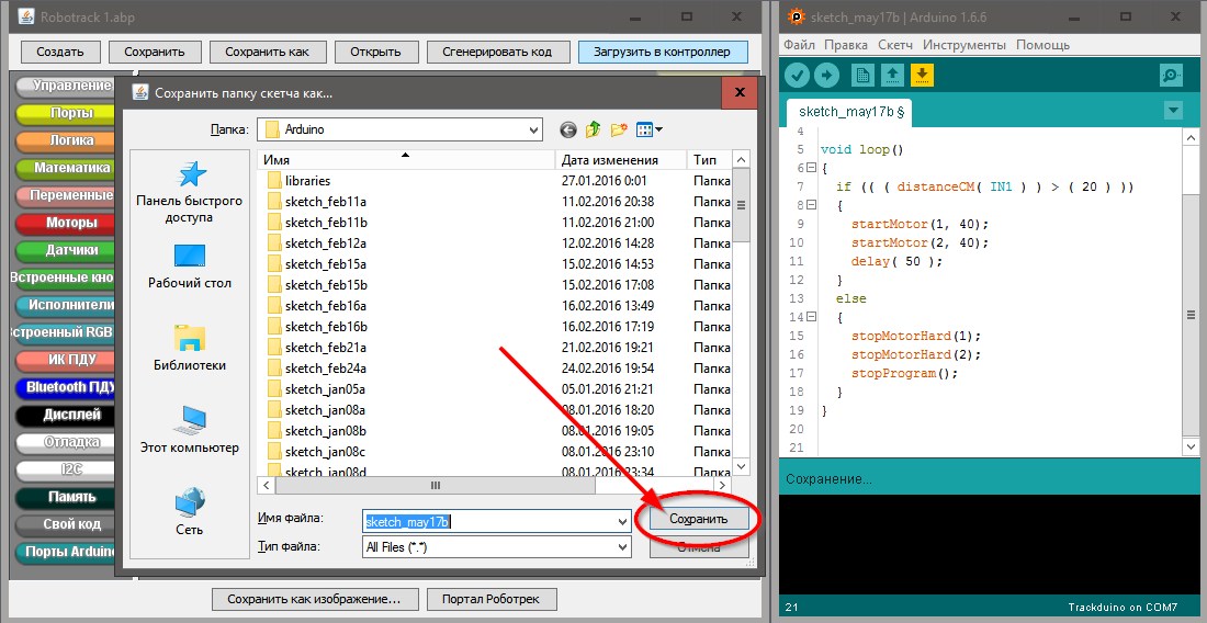
Important: From now on, changes to the text program are saved automatically before each upload. The visual program is not saved automatically. If you changed it, use Save as on the visual-environment toolbar.
After the text code is saved, compilation starts and its progress is shown in the text environment. The first compile may take up to a minute before uploading begins.
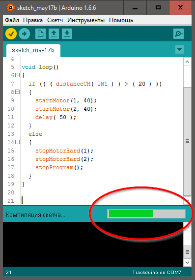
Compilation runs before each upload, but only the first compilation after launching the software takes noticeable time. Later compilations are almost immediate.
When compilation finishes, the program uploads automatically. The two yellow RX and TX LEDs at the lower-left of the board flash quickly while data is being transferred.
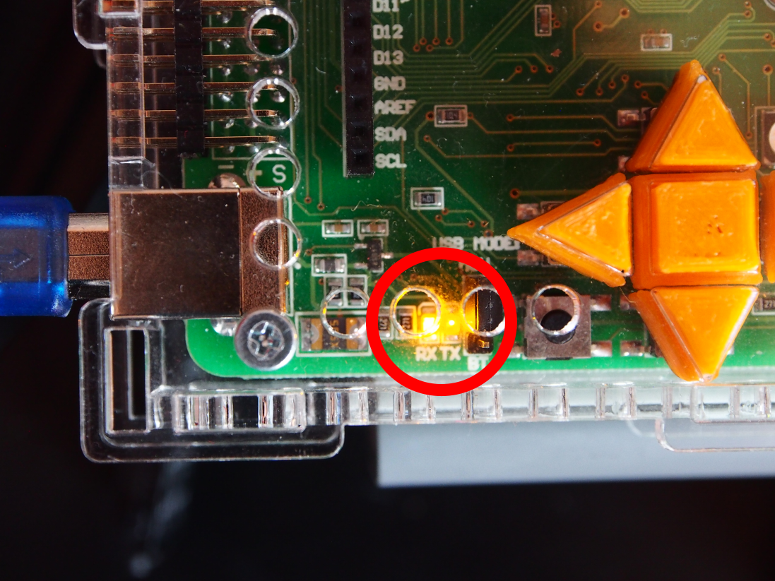
Uploading is complete when the LEDs stop flashing (wait at least one second before disconnecting the board) or when the text environment displays Upload complete.
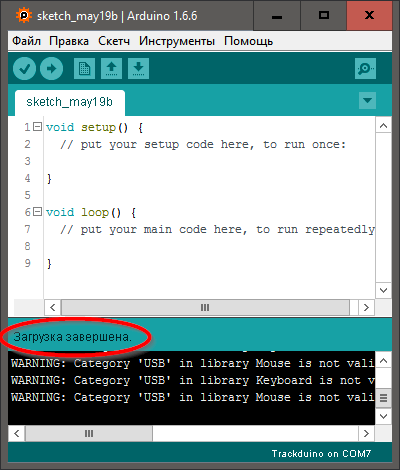
You can then disconnect the controller’s USB cable and assemble the model or connect its sensors. The cable can remain plugged into the computer.
Getting to know the controller
Main article: Trackduino.
The external-device ports are on the left and right sides of the controller.
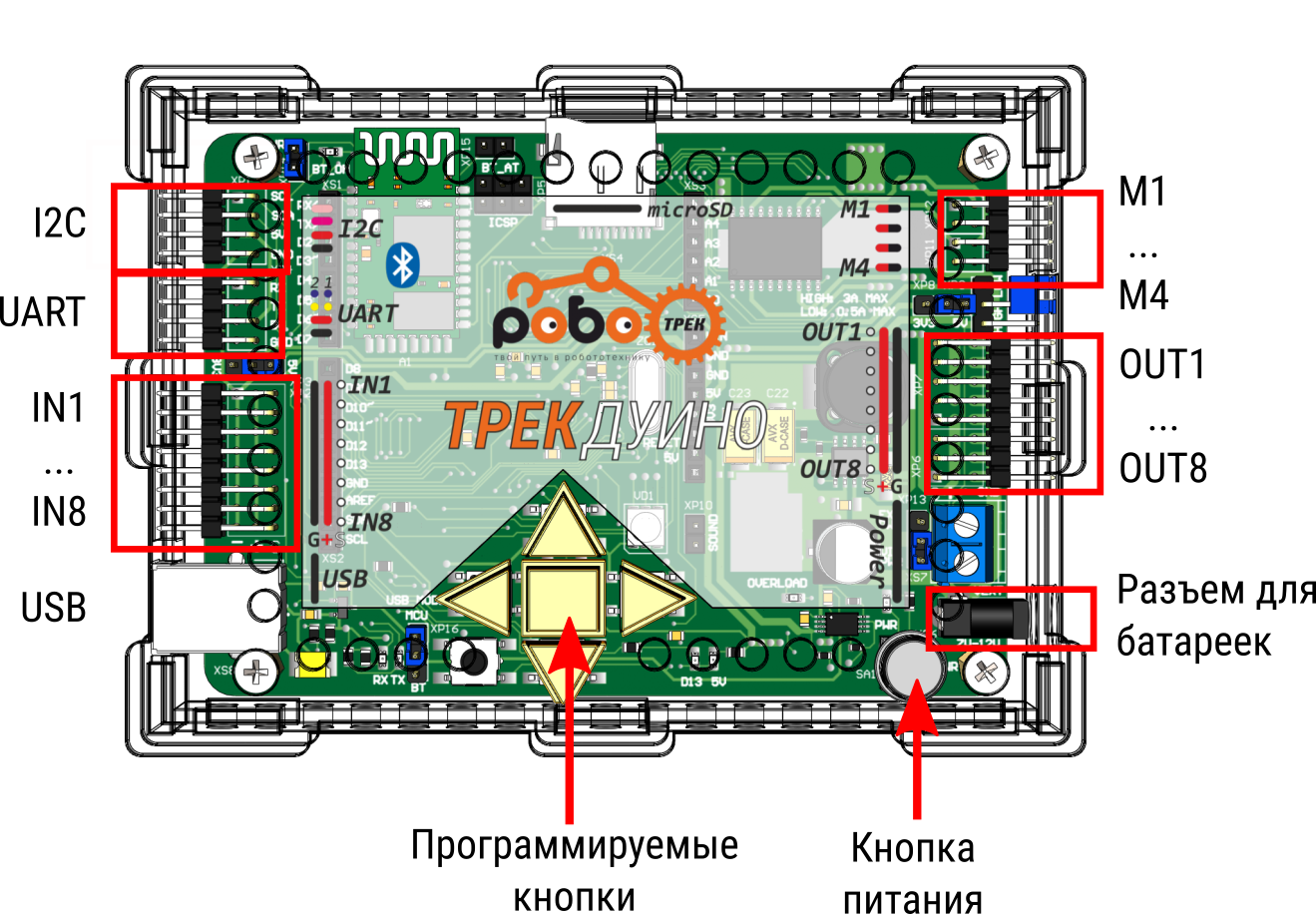
Left side:
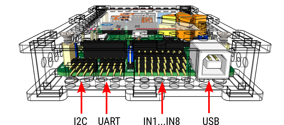
- USB port for connecting the controller to a computer.
- Two I2C ports for a position sensor (gyroscope/accelerometer).
- Two UART ports for a display.
- Eight IN ports for sensors, including:
Right side:
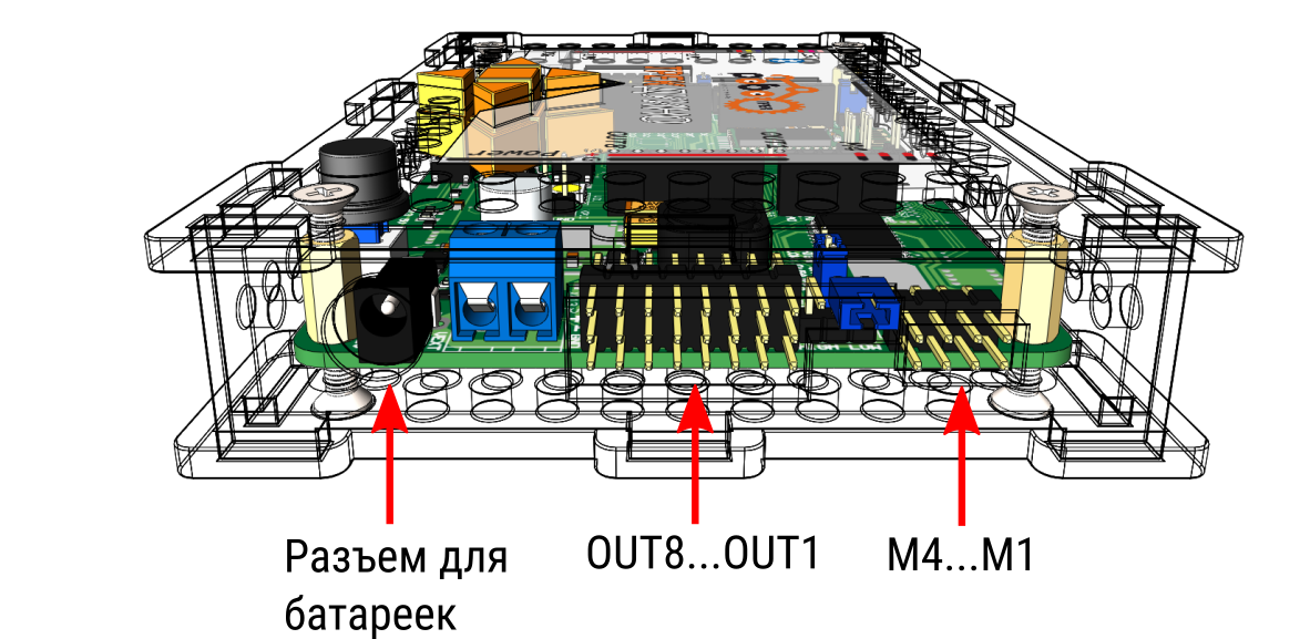
- External power connector for battery holders.
- Four M1–M4 ports for motors.
- Eight OUT ports for actuators, including:
Top: battery power on/off button (power stays on while USB-powered) and built-in programmable buttons.
Rules for connecting external devices
1. Connecting devices to IN and OUT ports
Observe connector polarity. Devices connected to IN and OUT ports use a three-wire black-red-white bus and the connector shown here.
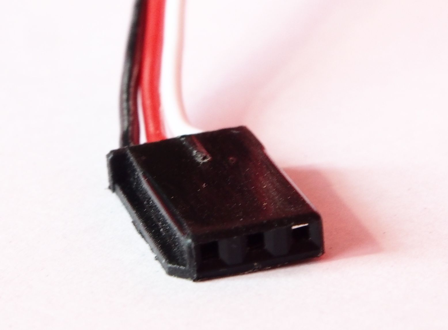
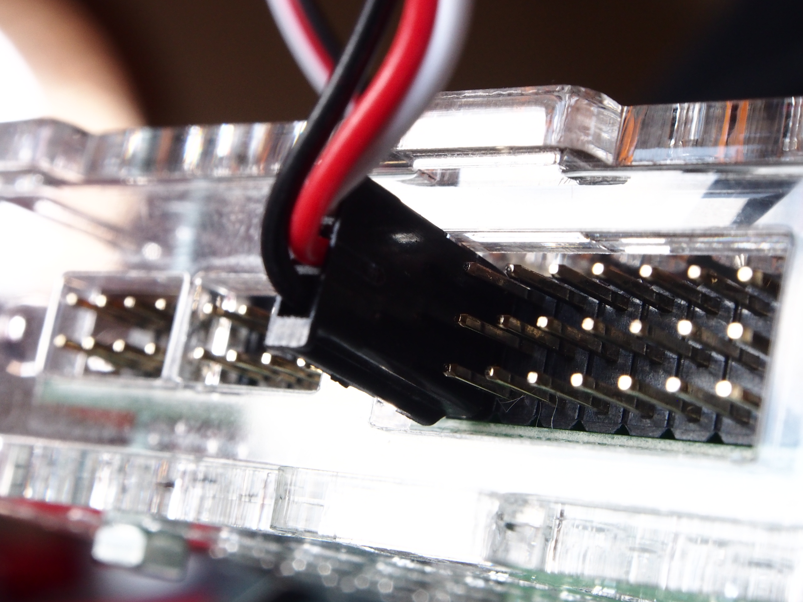
The connector has a ridge at one end, always on the black-wire side. When connecting, the ridge must face down.
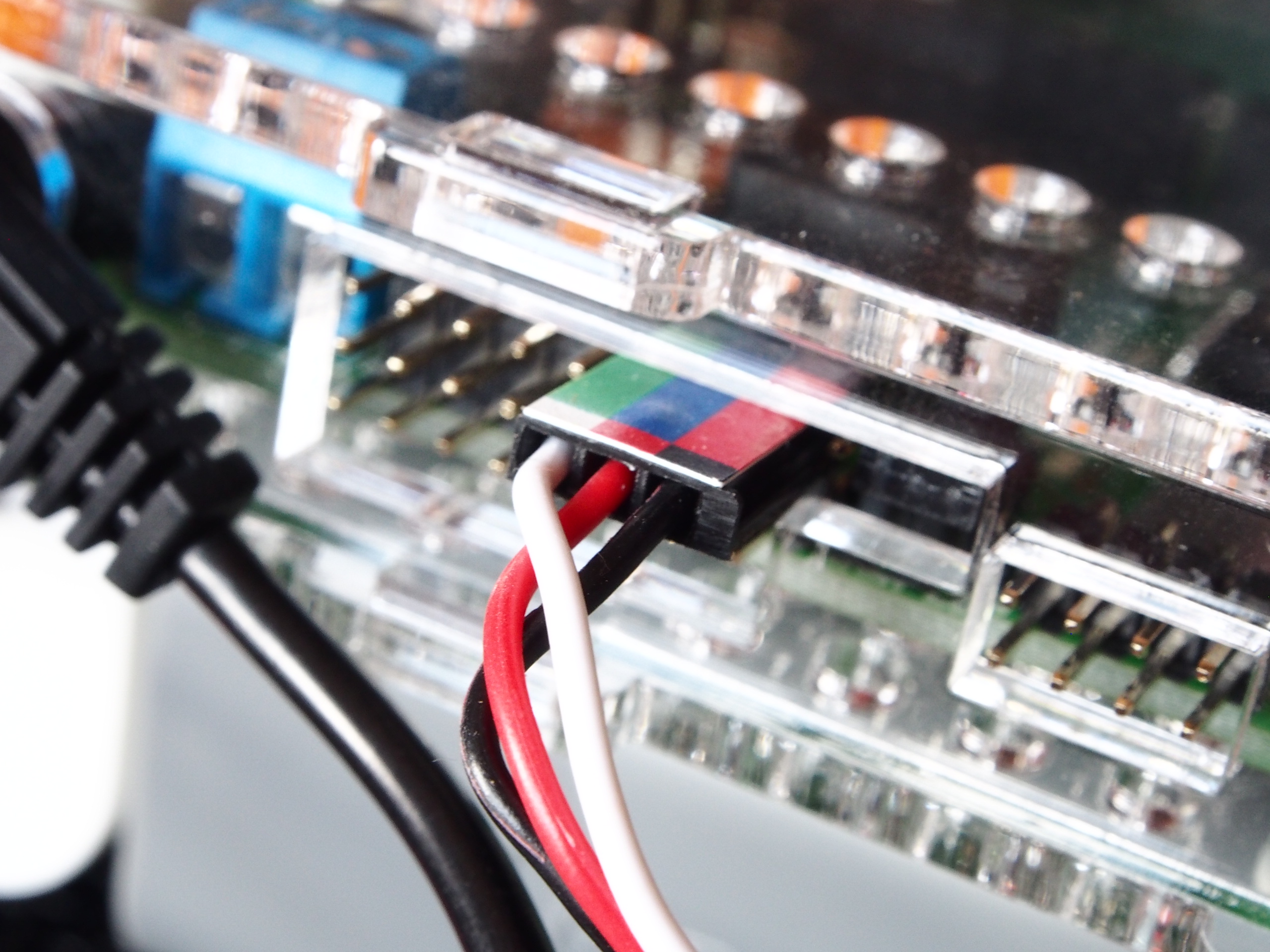
Connect external-device plugs vertically to IN and OUT ports, except for the color sensor’s RGB LED connector.
The color sensor’s RGB LED is the only connector that plugs horizontally into the top row of OUT ports.
2. Connecting motors
Main article: Motors.
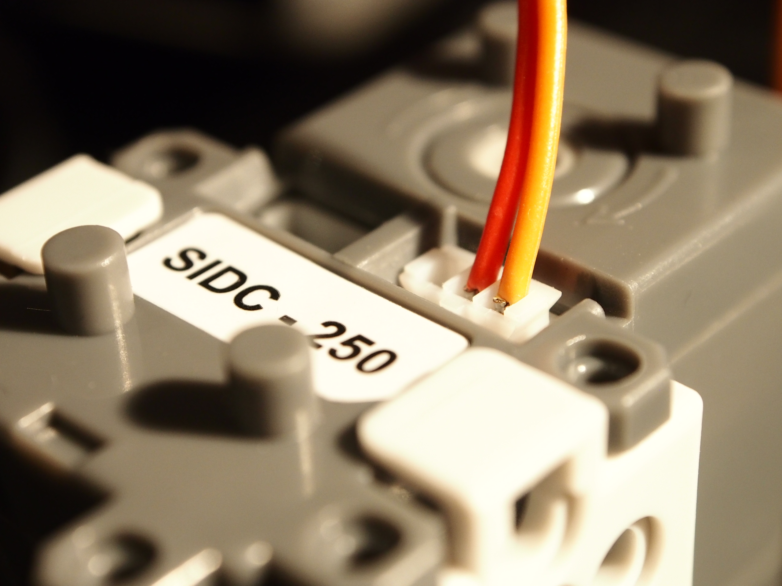
Motor connectors also plug into the controller vertically. Polarity only changes the direction of rotation; turning the connector 180° reverses the motor.
Insert the motor cable’s white connector into either motor socket as shown. Its special shape prevents incorrect insertion.
Insert the black connector fully into the required controller port.
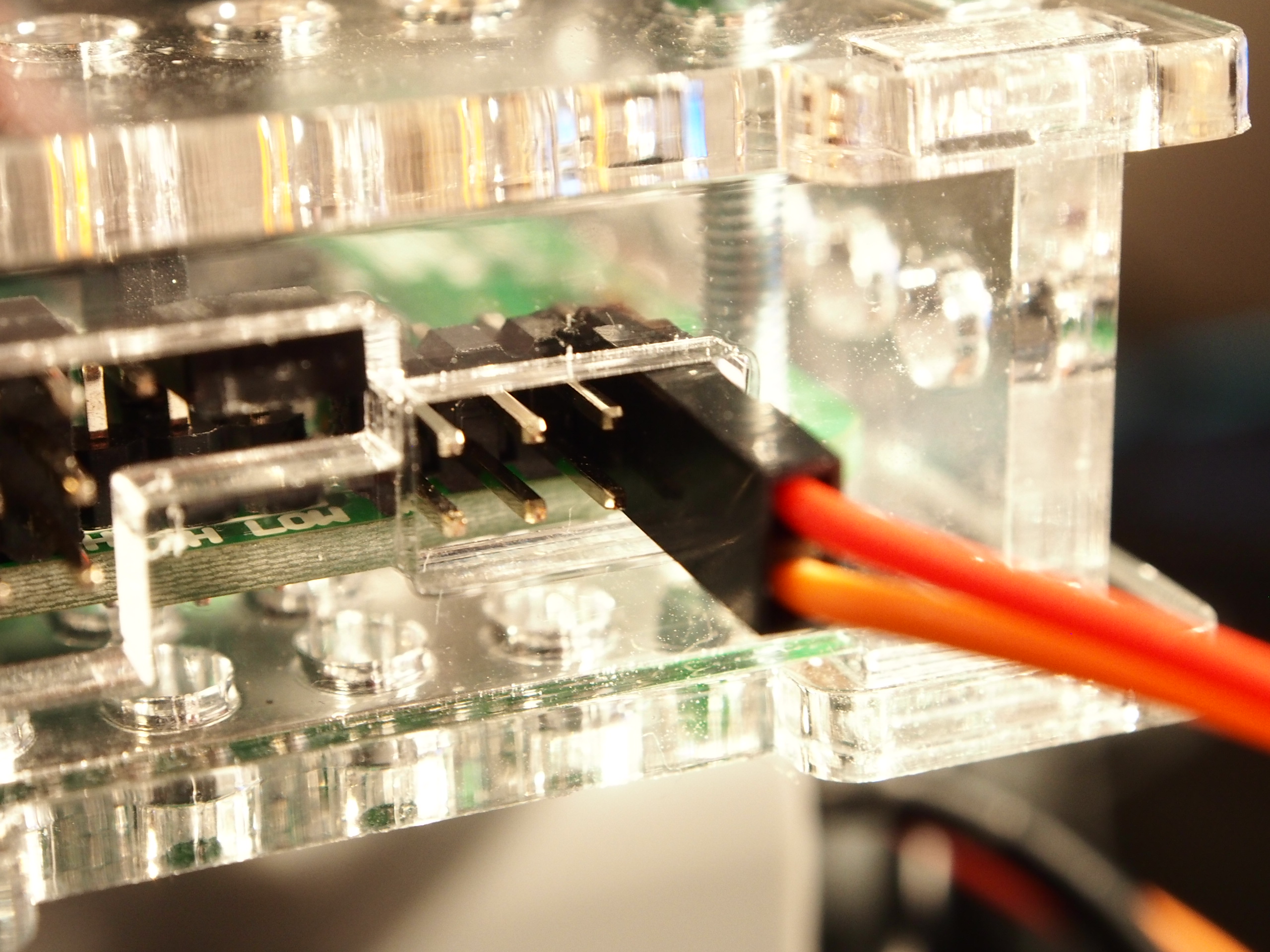
3. Connecting a display and position sensor
See the detailed instructions for connecting a display and position sensor to UART and I2C ports.
Using ready-made algorithms
Robotrack has developed about 80 ready-made algorithms for projects using a Trackduino controller, Sensors or Malysh Project resource kit, TFT LCD touchscreen display, and temperature sensor. Choose a project, select the required sensors and actuators, assemble the robot model, and upload the program to Trackduino. You can edit or extend an algorithm if needed.
Each algorithm has an accompanying text document that lists the required sensors and their ports, explains how the algorithm works, and includes a flowchart. Children build a model that performs the algorithm, and the teacher uploads the program to the microcontroller.
Algorithms are grouped by sensor and actuator. See the complete algorithm list and download the archive of ready-made algorithms. Open an algorithm’s explanatory document to learn how its program works.
To use an algorithm:
- Download and extract the ready-made algorithm archive.
- Choose an algorithm from the list for your project. For example, algorithm 2, “Explorer,” is suitable for a robot that avoids obstacles.
- Open the algorithm’s
.docxdescription in the corresponding archive folder and confirm that it does what you need. - Discuss the program sequence with the children using the flowchart.
- Find the listed components in the kit. If you do not recognize a component, find it in the component list on the Wiki home page to view its photo and learn how it works, connects, and is programmed.
- Assemble a model for the required function. For example, use a cart-style wheelbase and aim the ultrasonic sensor horizontally in the robot’s forward direction.
- Connect external components to the ports specified in the project. Motor order is flexible; for a cart-style robot, the left motor is usually connected to M1 and the right motor to M2.
- Attach battery holders with charged batteries and connect them to the controller’s external power port. If the controller LEDs turn on, switch it off with the power button.
- Connect the controller to the computer, launch the software, open the visual program, and upload it as described above.
- After uploading, disconnect USB, place the model on a level surface (preferably in the middle of the room), and switch on the controller. Use the same button to stop the robot.
- If the robot moves incorrectly (for example, spins instead of moving forward), reverse the polarity of the motor that is turning the wrong way: unplug its connector, rotate it 180°, and reconnect it to the same port. Reverse both if both motors are wrong.
- Modify the program if needed, upload it, and test again.