
MRT programming environment, version 1.2.4
MRT 1.2.4 requires the .NET Framework 3.5 component. It is included with Windows 10 but must be enabled:
- Open Control Panel from the Start menu (search for it or right-click Start).
- In Category view, open Programs.
- Select Turn Windows features on or off.
- Check .NET Framework 3.5 and click OK.
Download MRT: MRT 1.2.4 for Windows
Robotrack IDE
Download
Windows
Previous Windows versions
- Robotrack IDE 2.2.9 for Windows x86/64; compatible with NNTrack 1.1.3 and earlier
- Robotrack IDE 2.4.0 for Windows x86/64; compatible with NNTrack 2.1.1 and later
- Robotrack IDE 2.3.6 for Windows x86/64
- Robotrack IDE 2.2.5 for Windows x86/64
- Robotrack IDE 2.2.1 for Windows x86/64
- Robotrack IDE 1.4.4 for Windows x86/x64
- Robotrack IDE 2.0.4 for Windows x86/64
- Robotrack IDE 2.0.9 for Windows x86/64
- Robotrack IDE 2.1.9 for Windows x86/64
- New board driver for Windows
Linux (Astra, Alt)
Previous Linux versions
Change history
- Version 1.1.0: added the tutorial.
- Version 1.1.1: fixed an issue with the vibration sensor.
- Version 1.1.2: corrected lesson 39 in the tutorial and fixed a variable name.
- Version 1.1.3 (Neiro): added a separate Neurotrack add-on.
- Version 1.1.4: added support for the new TFT display firmware.
- Version 1.1.5: added blocks and an application for the neural interface.
- Version 1.1.6: updated the neural-interface application and fixed
display.cpp. - Version 1.1.7: added blocks for the Videretrack computer-vision resource kit.
- Version 1.1.8: increased the number of readings supported by the ultrasonic distance sensor to four.
- Version 1.1.9: added blocks for the Audiotrack MP3 module.
- Version 1.2.0: release notes.
- Version 1.3.1: fixed issues and added support for the new Robotrack PDU version.
- Version 1.4.4: fixed issues, added neural-interface window resizing and Artintrek blocks, improved neural-interface data collection, and updated the driver.
- Version 2.0.6: fixed issues, added blocks for code and arrays, and fixed the piezo emitter.
- Version 2.2.9: added NNTrack blocks, soft-manipulator blocks, Russian characters in strings, an electrical-engineering section, and a number-to-string block.
Overview
Robotrack IDE is a development environment based on Arduino IDE with an added visual programming environment. It lets you build programs from blocks without writing or editing code.
Robotrack IDE is fully compatible with Arduino boards and libraries. If you use Robotrack and Arduino kits together, you do not need to install separate IDEs.
The visual environment is based on Ardublock and works as an Arduino IDE plugin that generates C code from a visual program. The visual program structure usually corresponds closely to the text program structure, making it easier to move from block-based to text-based programming.
Installation
Windows: Download and run the installer, then follow its steps. When installation is complete, a program shortcut appears on the desktop.
Linux (Astra, Alt): Download and extract the archive.
- Astra: Follow the installation guide. When installation is complete, a shortcut appears on the desktop and in the Development section.
- Alt: Follow the installation guide. When installation is complete, a shortcut appears in the Programming section of the quick-launch menu.
System requirements
Windows: Windows 7, 8, or 10 (32- or 64-bit); 300 MB of free disk space; keyboard and mouse.
Linux Astra / Linux Alt: Linux Astra or Linux Alt; 500 MB of free disk space; keyboard and mouse.
Getting started and interface
When the program starts, the Arduino IDE and visual-environment windows appear next to each other and fill the screen. You can move and resize either window.
You can close the visual environment when writing programs in text, but do not close the Arduino window; doing so exits the program completely.
If you use only the visual environment, maximize it and minimize Arduino IDE. If you accidentally close the visual-environment window, reopen it from Tools → Visual Environment in Arduino IDE.
After the first launch, check that Arduino IDE has the correct board and port selected under Tools → Board and Tools → Port.
- Top toolbar:
- New: create an empty visual program.
- Save: save the current visual program.
- Save as: save the current program with additional settings.
- Open: open a visual-program file.
- Generate code: convert the visual program to Arduino IDE code, for example, to edit it manually.
- Upload to controller: convert the visual program to Arduino IDE code and upload it to the controller.
- Serial monitor: open the serial-port monitor.
- Bottom toolbar:
- Save as image: export the current program as a PNG image.
- Roborack portal: link to the Robotrack project portal with additional information about the software and construction kits.
- Block factory: contains the blocks used to build a program.
- Workspace: where you assemble the program.
Editing
Adding blocks
Open a block group, drag a block to the workspace with the left mouse button, and position its connector close to the connector on the block you want to join. Release the button. You will hear a click when the blocks connect successfully.
Deleting blocks
To delete one or more blocks, drag the block to be deleted beyond the edge of the workspace.
Copying blocks
Right-click a block and select Clone. A copy of the block and its child blocks appears in the workspace. If other blocks are attached below the selected block, they are cloned too.
Comments
Right-click a block and select Add comment. You can then move, hide, or delete the comment. Comments are not converted to Arduino IDE code.
Blocks
Block groups
Blocks are organized into groups in the block factory:
| Group | Description |
|---|---|
| Control | Program flow and branching, such as loops, conditions, delays, and transitions. |
| Ports | Direct access to IN and OUT ports: set a high or low voltage and read values. |
| Logic | Comparison and Boolean operators such as AND, OR, and NOT. These blocks return 1 or 0. |
| Math | Mathematical operations such as addition, subtraction, multiplication, and scaling. |
| Variables | Create and modify variables of different types. |
| Motors | Control motors and servomotors. |
| Sensors | Configure and read distance, color, IR, light, touch, fire, impact, encoder, microphone, magnetic-field, position, and temperature sensors. |
| Built-in buttons | Read the state of buttons on the board. |
| Actuators | Control actuators other than motors, such as an LED or buzzer. |
| Built-in RGB LED | Control the RGB LED on the board. |
| IR remote | Blocks for infrared remote control. |
| Bluetooth remote | Blocks for Bluetooth remote control using the Robotrack PDU app. |
| Display | Work with the display, including text and geometric shapes. |
| Debugging | Send data to a computer over UART and read data sent from the computer through a terminal. |
| I2C | General blocks for devices that use the I2C bus. |
| Memory | Read and write non-volatile memory: the microcontroller EEPROM and SD card. |
| Custom code | Add any lines of text code to a visual program. |
| Arduino ports | Access ports on the Arduino interface. |
Block types
Blocks can be classified by several properties.
Commands
Commands perform an action and return no value. Every program must contain at least one command. Commands have connectors at the top and bottom and connect only to other commands.
Commands can take function results or variables as arguments. A command that requires arguments has one or more connectors on its right side. A connector’s shape indicates the expected value type; attach a variable of that type or a function to it. Commands run one after another, from top to bottom.
Functions
Functions do not have top or bottom connectors. They can be used only as arguments to commands or other functions. The left connector’s shape indicates the returned data type:
| Left connector shape | Data type |
|---|---|
Rounded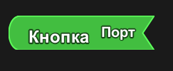 | Boolean: 0 or 1. |
Angled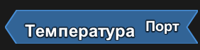 | Number. |
Rectangular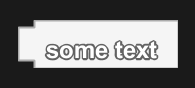 | String of characters. |
Curved | Character. |
Functions can be nested to any depth. Execution starts with the innermost block.
In this program:
- The distance sensor on port IN1 is read.
- The distance sensor on port IN2 is read.
- The two readings are added.
- The sum is divided by 2 to calculate their average.
- The average is scaled from 0–100 to 0–180, the servomotor’s operating angle.
- The servomotor moves to the resulting angle.
Editable and non-editable blocks
Commands and functions can have editable fields: either a list selection or text input. For example: